
10x500 мм машина для выравнивания стальной пластины высокоточная
- Категория: Metal Straightening Machinery >>>
- Поставщик: Haian,Zhengheng,Machinery,Technology,Co.,Ltd.
Поделиться:
Описание и отзывы
Трекер стоимости
| Месяц | Минимальная цена | Макс. стоимость |
|---|---|---|
| Sep-15-2025 | 107100.15 $* | 112455.63 $* |
| Aug-15-2025 | 106200.54 $* | 111510.61 $* |
| Jul-15-2025 | 89100.34 $* | 93555.87 $* |
| Jun-15-2025 | 104400.92 $* | 109620.33 $* |
| May-15-2025 | 90900.92 $* | 95445.1 $* |
| Apr-15-2025 | 102600.83 $* | 107730.33 $* |
| Mar-15-2025 | 101700.66 $* | 106785.54 $* |
| Feb-15-2025 | 100800.52 $* | 105840.86 $* |
| Jan-15-2025 | 99900.88 $* | 104895.60 $* |
Характеристики
National Invention Patent ( patent number: ZL201410077882.1)

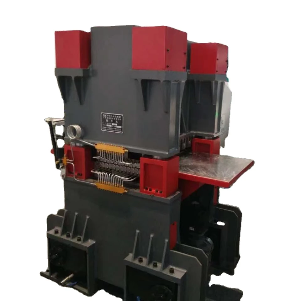
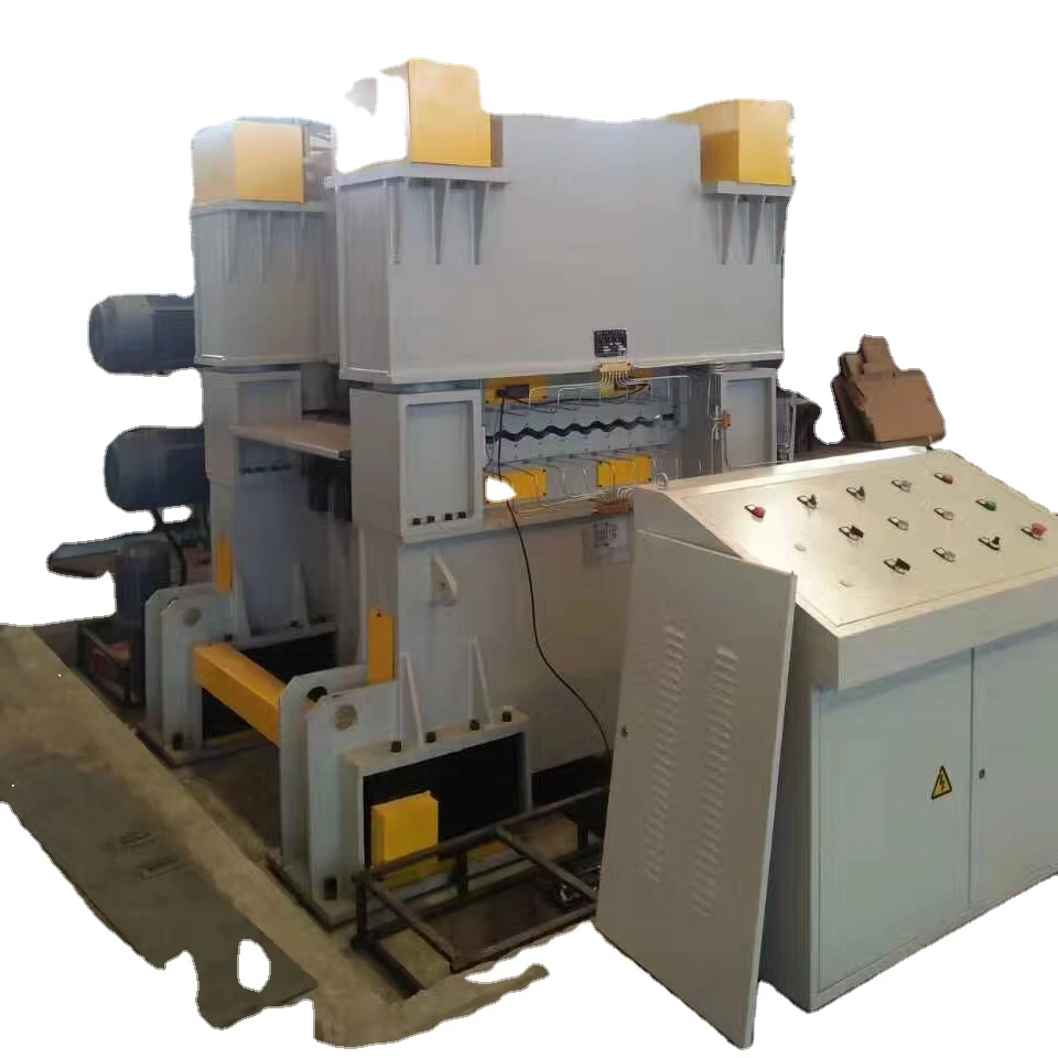
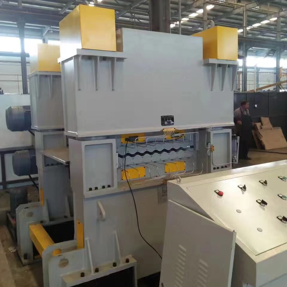
This machine is roll type sheet leveling machine. It belongs to ZHZZ series standard machine, which is with support construction. It is machine specially for plate cold leveling. The working principle is "Singer effect" , making repeat deformation between work rolls to make a variety of original curvature tends to be flat, so as to achieve the purpose of leveling. It is mainly used in metallurgy, metal structure, vehicle, ship, container, pressure vessel, chemical machinery manufacturing and metal material warehousing, plate distribution and other industry board. The user can use the machine separately, can also be used together with various plate processing equipment for a wider range of function extension.
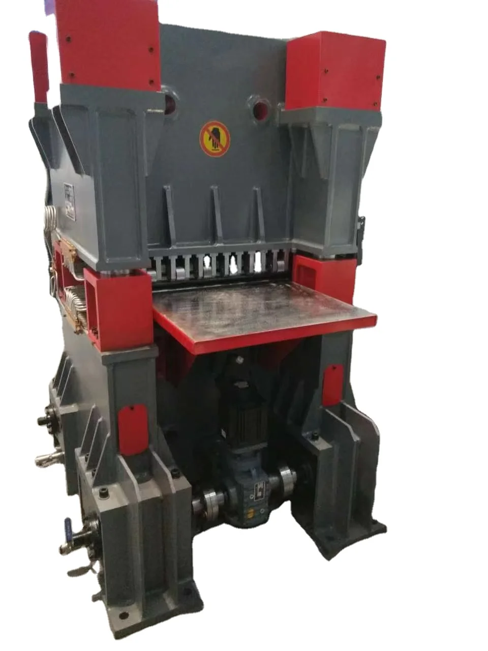
Power part
This machine is designed for a reducer+3-stage gear transmission and distribution drive, consisting of a motor, reducer, upper and lower gear power distribution box, etc. The main motor is directly connected to the reducer, transmitting power directly to the power distribution box of the cylindrical gear structure, and each leveling work roller has a driving force input. The output gear shafts of the upper and lower gearboxes are directly connected to the roller ends of the work rolls through key sleeves, and simultaneously drive the upper and lower work rolls to work.

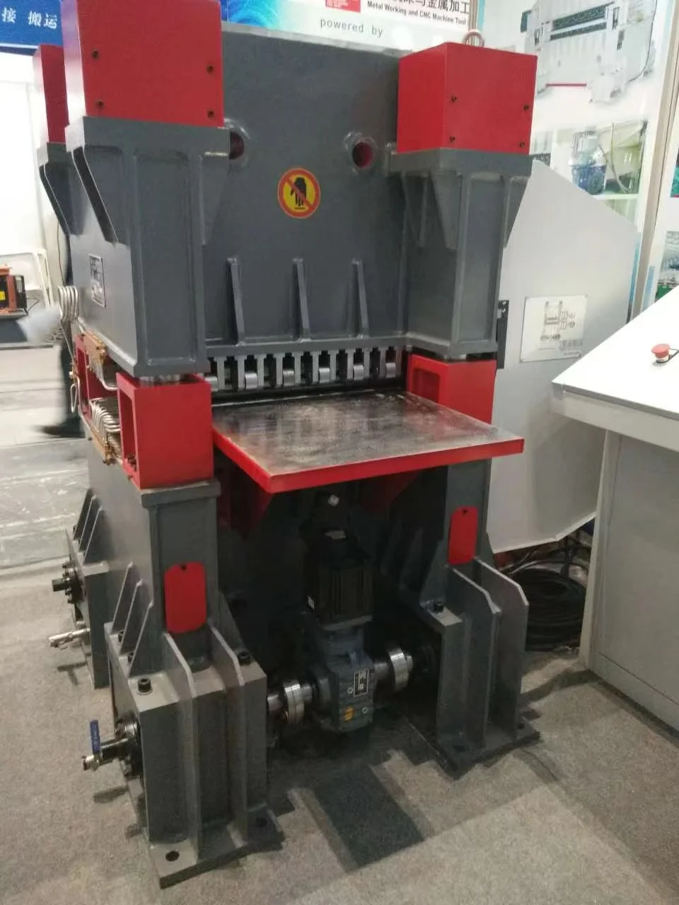
Host part
The main body of the machine is made of two steel structure girders, four column tie rods arranged at four corners, and a four fold roll assembly structure. It is composed of a movable upper beam welded by steel plate, a fixed lower beam, 17 leveling roll shafts (upper 8 and lower 9), upper and lower roll shaft seats, idler wheels, idler wheel seats, worm gear Worm drive upper roll lifting and boosting lower devices, etc.
Press down the power to place it at the bottom, and the pull rod connecting the upper and lower beams is pulled down to transmit the correction pressure. Including tie rods, movable upper beams, and fixed lower beams. The movable upper beam is equipped with an upper leveling roller, and the fixed lower beam is equipped with a lower leveling roller. The two ends of the movable upper beam are connected to pull rod seats at four corners, and the fixed lower beam is connected to the pull rod pressing power mechanism. The pull rod is located inside the pull rod seat, and there is a hinge pin device inside the pull rod seat. The pull rod is located inside the pull rod seat and connected to the pressing power device. The pressing power device causes the pull rod to move relative to the pull rod seat in the axial direction. When leveling steel plates that are difficult to level, the gap between the inlet and outlet can be adjusted as needed, the motor can be operated in the opposite direction, the direction of plate travel can be changed, and repeated rolling can be carried out to improve leveling accuracy and fully release material stress.
The upper and lower rows of leveling work rolls are each equipped with special support bearings and rollers, which sequentially support the leveling rolls to ensure that the leveling work rolls do not deform due to the correction pressure. The power transmission mechanism of the pull rod adopts a worm gear and worm mechanism with reliable performance and high transmission efficiency, including worm and worm gear. The pull rod is installed inside the worm gear and connected to the inner thread of the worm gear. The worm is connected to the outer tooth surface of the worm gear, and the thrust self-aligning roller bearing bears the axial load of the pull rod.
A hydraulic cylinder is installed between the upper and lower beams to balance and stabilize the upper beam, and to eliminate the clearance between the pull rod and the worm gear.
The connection between the pull rod and the movable upper beam is a hinge pin.
There are lifting holes on the movable upper beam.
Due to the above structure, this machine also has the following advantages:
a. This tension rod presses down the leveling machine, synthesizing the screw rod and bolt into a tension rod, and eliminating the design of end beams, connecting beams, columns, etc., simplifying the structure of the leveling machine.
b. This tension rod presses the leveling machine, and the tension rod is located at the outermost point of both ends of the movable upper beam, making it easy to control the balance of the leveling roller connected to the movable upper beam.
c. The swing mechanism at the upper end of the pull rod is designed to eliminate the displacement of the movable beam at the turning angle, and also facilitates positioning and fastening during the assembly process.
d. The thread clearance between the pull rod and the worm gear adopts a hydraulic cylinder.
e. The pull rod seat is designed at the four corners of the movable upper beam, and the pull rod seat includes hinge pins. Pin seat. By disassembling the upper shell of the fastening nut and pin seat at the upper end of the pull rod, the movable upper beam and the upper leveling roller system can be lifted up and separated from the fixed lower beam, making it extremely convenient to clean, maintain, and repair the leveling and supporting roller system.
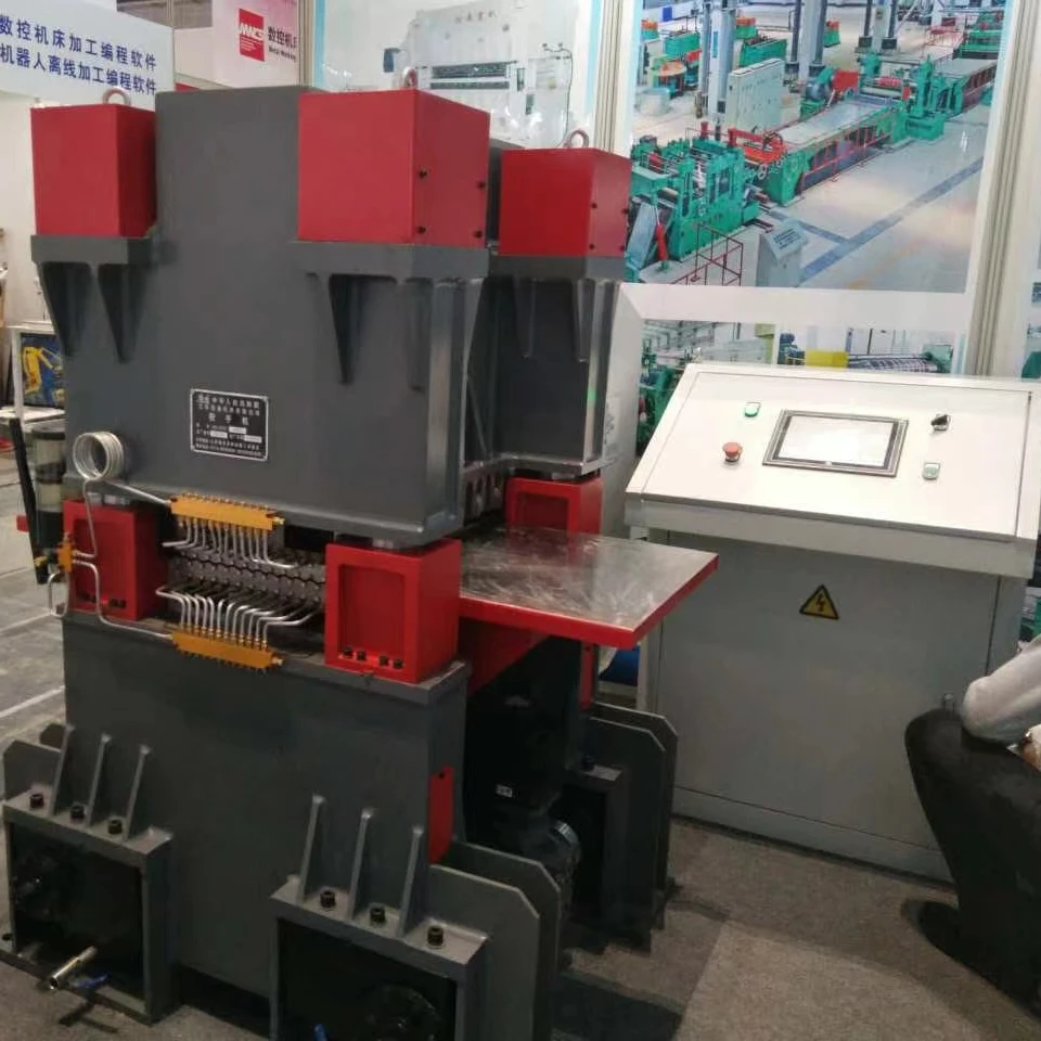
Control system and electrical system
The power supply for the electrical system of this machine tool is a 380V, 50HZ AC power supply, with a component control voltage of DC24V, an ambient temperature of -10 ℃ to 40 ℃, and a relative humidity of ≤ 80%.
The control and electrical systems meet the requirements specified in the bidding documents. It is centrally controlled by the electrical control console, and the electrical control part includes the console, control cabinet, and supporting components. Each motor in the main circuit uses a circuit breaker combined with thermal protection to achieve short circuit and overload protection, while the control circuit uses a fuse to achieve corresponding short circuit protection.
All electrical buttons that can achieve leveling function are arranged on the electrical control panel of the operation console, making it convenient to adjust the gap between the upper and lower roller openings.
Electrical control configuration: main electrical cabinet, console, touch screen, PLC, frequency converter, the system has automatic memory, call, and execution of working status and parameters.
Press down using a motor directly connected to a precision reducer, quickly lifting and pressing the upper beam.
1. System Overview
1) It can adjust the roll gap process parameters of the equipment after inputting relevant parameters such as material width, thickness, yield strength, etc. It can be called, stored, modified, and has the function of misoperation identification and warning. The CNC system should be reliably isolated from external signals, and its anti-interference ability should comply with national standards and relevant standards.
2) Equipped with a sensing digital display device, which can convert displacement models into electrical signals and be controlled by the control system. The lifting displacement of the work roller is displayed on the display screen of the operating platform with an accuracy of ± 0.1mm, and has a power outage memory function. The sensing device should ensure that the digital display is zero when the upper and lower roller busbars overlap.
3) The human-computer interaction interface can display the status of the device, I/O port status, abnormal alarm information, etc;
4) Electrical and electronic equipment has strong anti-interference ability and good moisture resistance. Various electrical indicating devices should be clear and eye-catching. The layout design of electrical components should be reasonable and aesthetically pleasing, with neat wires and clear markings.
5) The electric control cabinet adopts reliable dustproof sealing, which can effectively prevent dust intrusion and water splashing. The protection level is IP54 or above, and it ensures good heat dissipation effect. All electrical circuits are marked with wire numbers.
6) The control system displays fault information, and the electrical devices have safe and reliable grounding devices and safety devices.
7) The control panel buttons are centrally controlled and equipped with power indication, as well as current and voltage display.
2. System Function Description
1) Working method: one-way leveling.
2) The operating console adopts a movable suspension type or is fixed on the rack, which can facilitate all control operations, and is equipped with an emergency stop button on the column.
3) The equipment has sufficient stiffness and stability, runs smoothly, and has good seismic resistance. After long-term operation, there is no decrease in leveling accuracy or main performance parameters due to poor rigidity of components such as rollers or body.
4) The structural design of the equipment is reasonable. Before the overhaul period, it can compensate for any decrease in leveling accuracy caused by wear and tear. After the overhaul, the original accuracy of the equipment can be restored. The adjustment process is simple, fast, and lightweight.
3. Safety protection
1) The protection level of the electric control box casing is IP54. The door of the electric control cabinet is equipped with sealing strips to prevent workshop dust from entering the cabinet.
2) The equipment is equipped with safety protection interlocking devices and overload, overvoltage, overcurrent, short circuit, open circuit, and leakage protection devices, as well as machine tool protection devices in case of power outage or unexpected shutdown.
3) The various mechanisms of the machine tool have complete and reliable interlocking, safety protection, and fault alarm functions to prevent accidents from causing equipment, workpieces, and personal safety. All electrical devices are equipped with safe and reliable grounding devices.
4) The equipment is equipped with upper row work roll displacement position limit switches, which automatically stop when the work rolls reach the upper and lower limit positions to avoid excessive displacement and damage to the machine.
5) For the safety of the operator, safety light curtains are installed at the inlet and outlet to effectively carry out safety operations. When the human body approaches the danger zone, the machine automatically stops.
6) Equipped with three color lights, safety signs are set up in hazardous areas according to the requirements of Chinese GB18209 and GB2894, and safety colors are set up in hazardous areas according to GB2893.
lubrication system
1. Reliable lubrication is provided between each friction pair of the equipment, and important lubrication parts should have fault detection, oil level, and lubrication alarm functions to protect the safe operation of the equipment. Necessary dust prevention devices are necessary to ensure long-term stable operation of the equipment.
2. Centralized lubrication is adopted, and the rotating parts of the upper and lower work rolls can be effectively lubricated. Program control is adopted, and automatic lubrication can be carried out by activating the lubrication button. The structural distribution and lubrication method of each lubrication point are reasonable, and the sealing is ensured to be reasonable and reliable without leakage.
Specific design description:
1) The upper and lower gearbox oil pools are immersed in oil for lubrication.
2) Thin oil splashing lubrication in the gearbox oil pool.
3) Leveling rollers and supporting rollers are lubricated with concentrated dry oil.
4) Immersion lubrication of the worm gear box oil pool.
5) Each lubrication point, such as the remaining screws, guide surfaces, and movable pins, is separately supplied with oil, and is manually lubricated regularly.
Process assurance measures
This machine is designed to meet the requirements of sufficient rigidity and strength, while also further strengthening and optimizing important components such as the frame, to ensure that it meets the user's requirements for precision leveling of high-strength metal sheets.
1. The machine base, upper and lower beams, brackets, and brackets are strictly welded according to the process requirements, and the overall aging treatment is carried out after inspection (at least 8 hours in the furnace). Tempering is used to eliminate internal stress and ensure the accuracy of the unit assembly.
2. The upper and lower roller shaft seats and support wheel seats are precision cast steel parts, which are subjected to overall aging treatment after rough machining (at least 8 hours in the furnace) to eliminate internal stress and ensure accuracy for a long time.
3. The leveling roller material is GCr15, and the support wheel material is GCr15. Leveling roller shaft, supporting wheel after forging → rough turning → quenching and tempering → precision turning → medium frequency quenching → low-temperature tempering → electroplating and precision grinding. The surface of the leveling roller has a medium frequency quenching hardness of HRC58-62, and a single side quenching depth of ≥ 5mm. The quenching hardness of the support wheel is HRC50-55, and the single side quenching depth is ≈ 3mm.
Brief description of the main structure and functions of the equipment
Frame
Adopting computer optimized design, the overall appearance of the machine is beautiful and elegant. The fuselage adopts a Q235B low-carbon steel plate welded combination structure, which is tempered and stress relieved after welding, and has good seismic resistance, sufficient strength and stiffness. The machining process of the rack: CNC cutting and cutting → processing grooves for various plate-shaped parts → welding → overall tempering → boring and milling processing,

Movable beam
The upper row of work rolls of the machine are assembled on the movable upper beam, and the gear reducer motor drives the worm gear and worm to lift and press it down. Adopting computer optimized design, with high strength and good rigidity, and tempering treatment after welding

Pressing mechanism
The adjustment of the gap between the inlet and outlet rollers is composed of a dedicated gear reducer directly connected to the motor, a worm gear pair, etc. The worm gear pair drives the pull rod to adjust the radial clearance between the upper and lower leveling rollers (the gap between the front and rear inlet and outlet rollers). According to the machine load situation, the system automatically realizes rapid lifting, pressing, and constant speed work progress.
Compared with the traditional discharge frame structure form of leveling machine, this design can have enough space to fully press down the rigidity of the pull rod according to the correction pressure, ensuring that no matter how the leveling pressure load changes, the gap between the upper and lower rollers remains almost unchanged. It can adjust the relative position of the angle between the upper and lower working rollers at will, and leveling different thicknesses, materials, and shapes of plates to achieve the best flatness effect

Work roll
The work roll is the main key working part of the machine. The material of the work roll of this machine is GCr15 forged piece. After rough turning, it is quenched and tempered to HB250~280. After fine turning, the surface is subject to medium frequency quenching and fine grinding. The medium frequency quenching hardness is HRC58~62.
In order to facilitate the maintenance and upkeep of the leveling work roll and support wheel, this machine has designed the roller shaft seat and work roll into a structure that is easy to disassemble. Loosen the fastening bolts of the roller shaft seat, take out the shaft seat at the unpowered end towards the axial direction of the roller, and then directly pull out the leveling work roller one by one, and then disassemble the supporting supporting roller

Lower crossbeam
This component also serves as the overall chassis of the machine, adopting computer optimization design and tempering treatment after welding. It has good seismic resistance, and its strength and rigidity meet the straightening needs of the plate


Certificate

Machining Equipment


