RGBW RGB PWM управляющий сигнал 24 CH Канал
- Категория: >>>
- Поставщик: Shenzhen,Magic,Led,Lighting,Co.,Ltd.
Поделиться:
Описание и отзывы
Трекер стоимости
| Месяц | Минимальная цена | Макс. стоимость |
|---|---|---|
| Sep-18-2025 | 0.72 $* | 0.89 $* |
| Aug-18-2025 | 0.57 $* | 0.76 $* |
| Jul-18-2025 | 0.73 $* | 0.25 $* |
| Jun-18-2025 | 0.82 $* | 0.28 $* |
| May-18-2025 | 0.74 $* | 0.41 $* |
| Apr-18-2025 | 0.30 $* | 0.97 $* |
| Mar-18-2025 | 0.43 $* | 0.85 $* |
| Feb-18-2025 | 0.68 $* | 0.21 $* |
| Jan-18-2025 | 0.50 $* | 0.50 $* |
Характеристики
Product Description
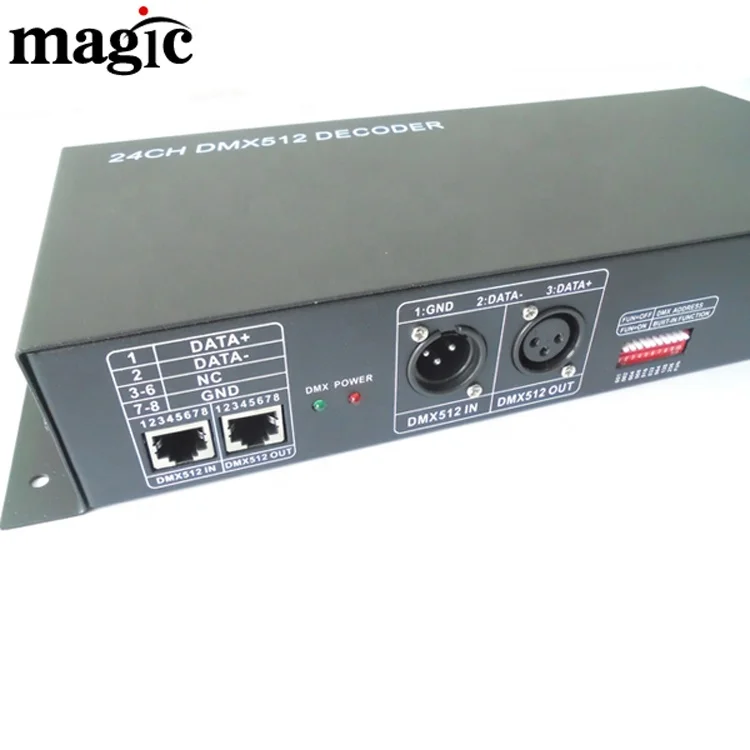
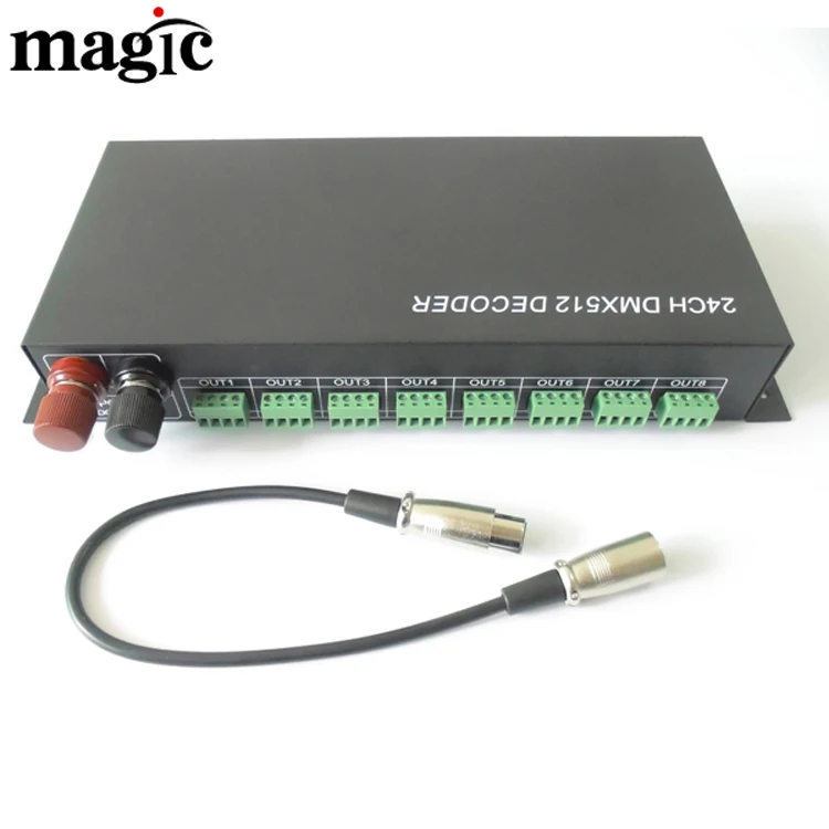
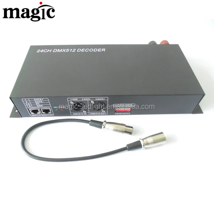
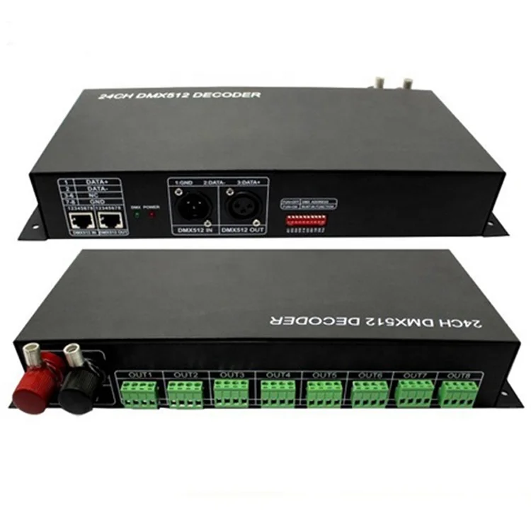
PWM Control Signal 24 Channels DMX512 Decoder For RGB LED Strips
24 Channel DMX512 Decoder
Summarization
The decoder adopt the advanced micro-computer control technology and converted the DMX512 digital signal widely used in international to the analog control signal. 1~24 channels output for option and each channel able to achieve 256 gradations of controlling, and also it can be used as the connector of PC digital light controller and analog light modulator. It is mainly used for the controlling of buildings & lights applied LED.
Technical Parameters
Decode channel: | 24 channel |
Supply voltage: | +12~24V |
External dimension | L340*W142*H57mm |
Working temperature | 0-70℃ |
Packing size | L350*W180*H65mm |
Net weight | 1.5kg |
Gross weight | 1.6kg |
Power consumption | <0.25A(12V); <0.30A(24V) |
Signal input | DMX-512 Standard digital signal |
Signal output | 0~24V, Max. 2A /CH |
Power output | 12V:<576W, 24V:<1152W |
External Dimension


Interface Specifications

- 1 DMX Signal input interface RJ45
- 2 DMXSignal output interface RJ45
- 3 Address setting interface
- 4 Drive output interface
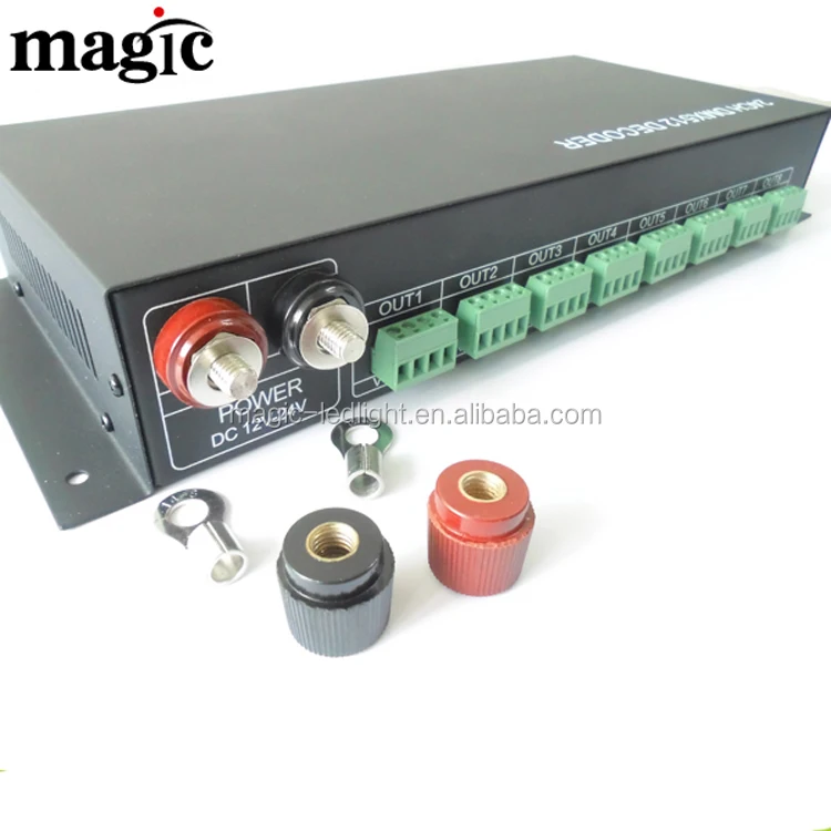
- 5 Power input interface
- 6 XLR 3 input male-end
- 7 XLR 3 output female-end
- DMX Signal Interface:

1: DATA+ 2: DATA- 3-6: NC 7-8: GND

1: GND 2:DATA 3:DATA+
- Address code setting on/off:
Please see the operating instruction next page.
- Power input interface:
DC12~24V input,supplied power with the decoder and the lamps it takes.
- Drive output interface:
Common in anode-V+ and with 8pcs of V+ interface & 24pcs of R, G, B output interface. Not only does it apply to the various of LED module in full-color & mono color, but also it can self-trimming the output current based on the load of LED module.
Remark:
Connect the anode and RGB wire of common anode RGB module to the output interface of decoder directly; Connect the anode wire of single-color module to V+ on decoder, and connect the cathode wire to one of RGB pin according to the LED's color; Connect several colors single-color module to one decoder, please connect their anode wires to V+ pin on decoder.
Direction for use
- Connecting of DMX-512 Signal Cable:
DMX signal cable used the CAT-5 cable,and DMX signal tells positive(+) from negative (-). While welding the DMX signal cable plug, there must pay much attention to know positive (+) from negative (-), and then connect the DMX512 signal cable with the corresponding input interface of DMX512 decoder correctly.
- DMX-512 address code set:
DIP switch of DMX512 decoder is with the function of writting the binary system and reading the DMX512 address code. DMX512 decoder is a decoder with 24 channels, When it is on-line job, the second DMX512 decoder should be set the address code as the 25th channel. The 10th bit is TERM and will be the terminal while it is off.(Only used for the signals circuit setting).The bits from1 to 9 of DIP switch are as the key of writing DMX address code, 1 is LSB and 9 is MSB; total 512 address codes. The initial address code is the DMX signal received by the No.1 channel of decoder, Calculational formula:[ Sum of 1~9 bits of DIP switch ] = DMX initial address code Set the n(th) bit of DIP switch up(set to“1”)to get the value of such bit; Set the n(th) bit of the DIP switch down “0”),so the value of this bit is 0.
Note:The 10th bit is the terminal.
- Points for attention in installing and using
Principle in installing & using:
- The input voltage should be limited in rated range.
- Do not use it by over load.
- Installed in suited environment.
- The driver can not be setting in high temperature or wet conditions
- We recommend three ways to take away the heat as follows
①Bared in moving air
②Put in a big enough space for taking away the heat
③Fixed on big metalline board, and make sure they are contacted well
Points for attention in installing and using:
- The reliable length of the line is 200m, please try to put the controller close to the decoder so as to avoid the signal become weak in using with the controller.
- Recommend to use the STP with the characteristic impedance of 120Ω
- It is better to use one bus for the signal line, and join up with the in/out splice of the decoder.
- Make sure to fix the signal line to the splice of decoder
- Please try to keep the decoder close to the light, if the light is over 5m, it is better to re-connect the light and decoder.
- If there are several lights connected in series, please make sure the splice is firm and impervious joint.
- Signal line and power line of lamps should be far away fromhigh voltage lines

Detailed Images


Connect Diagram