MCP DCL-7000-набор для цифрового логического


Поделиться:


Цена:32 395,30 ₽*

Количество:


Описание и отзывы


Трекер стоимости

Месяц Минимальная цена Макс. стоимость
Aug-18-2025 41142.14 $* 41965.72 $*
Jul-18-2025 33367.33 $* 34034.96 $*
Jun-18-2025 40494.49 $* 41304.87 $*
May-18-2025 40170.14 $* 40973.71 $*
Apr-18-2025 32071.77 $* 32712.67 $*
Mar-18-2025 39522.96 $* 40312.79 $*
Feb-18-2025 39198.11 $* 39982.17 $*
Jan-18-2025 38874.86 $* 39651.29 $*

Характеристики

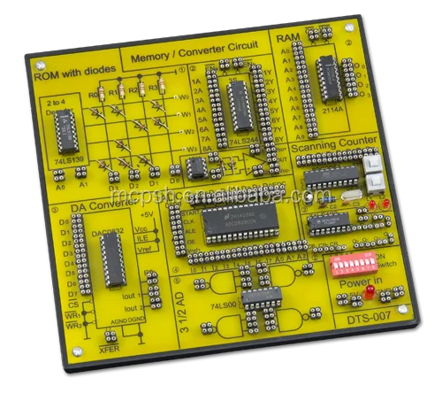
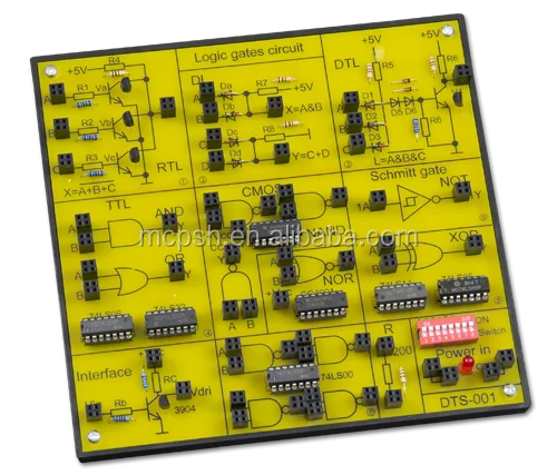
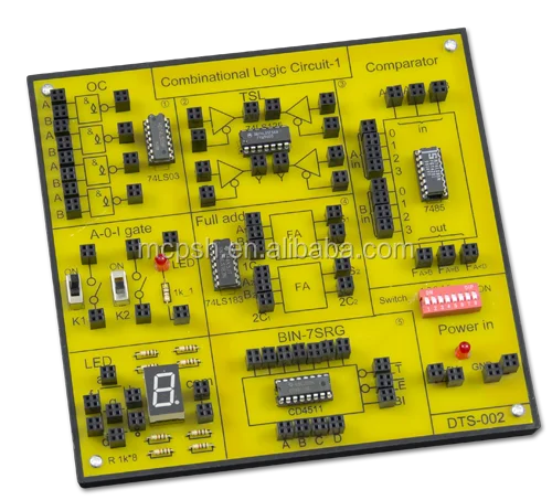
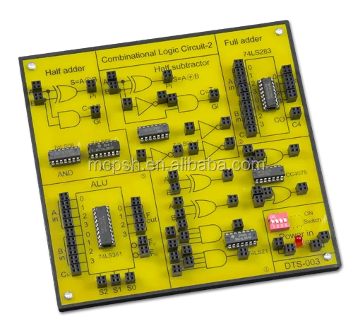
DCL-7000 DIGITAL CIRCUIT LABORATORY


Features

.Seven circuit boards form 19 experiments. 
.Suitable for combinational logic, sequential logic,and microprocessor circuit experimentation and design.
.Ideal tool for learning the basics of digital logic circuits.
.Step-by-step exercises and application.
.Integrated training system, with complete <INSTRUCTION>.
.Combination with M21-7000 digital-analog training system as main unit. 
.Step-by-step exercises and application .
.Expandability and flexibility of experiments greatly increased by large breadboard.
.Board can be changed easily. 


    The DCL-7000 digital circuit laboratory is a comprehensive and self-contained system suitable for tuition and experimentation with a range of digital electronics circuits. All necessary equipments for digital logic experiments such as power supply, signal generator, switches and displays are built-in on the main unit. The 7 circuit boards cover a wide variety of essential topics in the field of digital logic. It is a time and cost saving device for both students experiment and researchers interested in developing and testing circuit prototypes.


 THE FULL LIST OF EXPERIMENTS PERFORMED USING DTS-001 ~ DTS-007
 
Experiment 1
Experiment 2
Experiment 3
Experiment 4
Experiment 5
Experiment 6

Experiment 7
Experiment 8
Experiment 9
Experiment 10
Experiment 11
Experiment 12
Experiment 13

Experiment 14
Experiment 15
Experiment 16
Experiment 17
Experiment 18
Experiment 19
Transistor Switching Characteristics
Logic Function and Parameter test of TTL Integrated Logic Gate
Logic Functions and Parameter Test of CMOS Logic Gate
Verify Function of Logic Gate
Integration Logic Circuit Connection and Drive
Applications of TTL Gates with Open-collector Outputs and Tri-state Outputs
Digital Comparator Circuit 
Arithmetic Operation Circuit
Parity Generator
Encoder and Decoder 
Data Selector and Distributor
Use Gate to Produce Pulse Signal (Multivibrator) 
Monostable Trigger and Schmitt Trigger (Pulse Delay and Waveform Shaping Circuit)
555 Timer and Its Application
Trigger (flip-flop) and Its Application
Shift Register IC and Its Application
IC Counter and Its Application
Random Access Memory 2114A and Its Application
D/A and A/D converter
 
MAIN UNIT M21-7000
 

SOLDERLESS BREADBOARD

Interconnected with 2820 tie points nickel plated contact,fitted all DIP sizes and all components with lead and solid wire AWG # 22-30 (0.3-0.8mm).It can be changed and replaced for different purpose and can be connected with demonstration panel. Therefore, it is very convenient for both teachers and students.
DC POWER SUPPLY
A. Fixed DC output+5V, 1A
B. Fixed DC output-5V, 1A
C. Variable DC output0V to +15V, 1A
D. Variable DC output0V to –15V, 1A

POTENTION METERS

A. Variable resistor VR11kΩ
B. Variable resistor VR2100kΩ
FUNCTION GENERATOR
Frequency range1Hz-10Hz
10Hz-100Hz
100Hz-1kHz
1kHz-10kHz
10kHz-100kHz
AmplitudeSine wave output:0-10 Vpp variable
Triangle wave output:0-10 Vpp variable
Square wave output:0-10 Vpp variable
TTL mode output:4 Vpp

TWO DIGITS OF 7 SEGMENT LED DISPLAY

TWO PULSE SWITCH2 pcs pushbuttons contain switches debouncer for eliminating the bounce caused by switch from“open” to“close” or from“close” to“open”position.
SIXTEEN DATA SWITCHES16pcs toggle switches and corresponding output point. When switch is set at “down”position,the output is LO level; contrarily, it is to be HI level while setting at “up”position.
SPEAKER2-1/2 inch diameter, 8 ohm/0.5W to be used for load.
FOUR CHANNEL ADAPTORBoth of the two banana sockets' and two BNC jacks' point tips are changeable. It is suitable for M21-7000 to be connected with peripherals.
SIXTEEN BITS LED DISPLAY16 red LED's separate input terminals. The LED will be lighted up when input is at “HI level” ,and it will be turned off when it is at no input or at “LO level”.
UNIVERSAL CONNECTOR FIXED HOLDER
It reserves universal connector fixed holder on the panel in order to be connected with various universal connectors,
which are available
(1) Straight header 60 pin
(2) Card edge connector 2.54mm 62pin
(3) D sub25 pin connector, male & female
(4) Card edge connector 3.96mm 56pin
(5) Dip sockets connector 28 pin & 40 pin
  
 DTS CIRCUIT BOARD


DTS-001

DTS-001

DTS-002
DTS-002
 DTS-003
DTS-003
DTS-004
DTS-004
 DTS-005
DTS-005
DTS-006
DTS-006
 DTS-007
DTS-007
 
 GENERAL
 1. Accessories
(1) Power cord
(2) Pin leads: 10cm 20pcs, 20cm 20pcs
(3) User manual+ instruction of analog circuit experimentations

2. INPUT VOLTAGE: 110~127VAC±10% 60Hz, 220~240VAC±10% 50Hz Switchable

3. DIMENSIONS:
(1) Main unit (W×H×D): 258×95×334mm
(2) Circuit board: 165×170mm

4. WEIGHT:
(1) Main unit: 4.5kg
(2) Circuit board: 0.4kg×7

Данные ресурс не является интернет-магазином, а лишь содержит ссылки на международную торговую площадку Alibaba.com