


6 цветов для
- Категория: Офсетные принтеры >>>
- Поставщик: Wuxi,Yingrun,Machinery,Technology,Co.,Ltd.Wuxi,Ltd.
Поделиться:
Описание и отзывы
Трекер стоимости
| Месяц | Минимальная цена | Макс. стоимость |
|---|---|---|
| Sep-18-2025 | 19219043.35 $* | 20179995.73 $* |
| Aug-18-2025 | 19057538.4 $* | 20010415.27 $* |
| Jul-18-2025 | 15988951.73 $* | 16788399.47 $* |
| Jun-18-2025 | 18734529.98 $* | 19671255.94 $* |
| May-18-2025 | 16311961.24 $* | 17127559.97 $* |
| Apr-18-2025 | 18411520.96 $* | 19332096.79 $* |
| Mar-18-2025 | 18250015.3 $* | 19162516.15 $* |
| Feb-18-2025 | 18088511.80 $* | 18992937.55 $* |
| Jan-18-2025 | 17927006.35 $* | 18823356.23 $* |
Характеристики
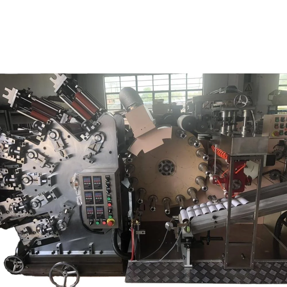
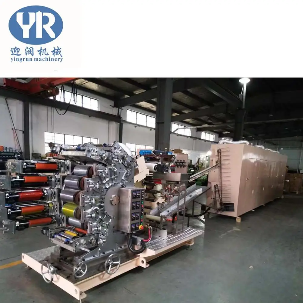
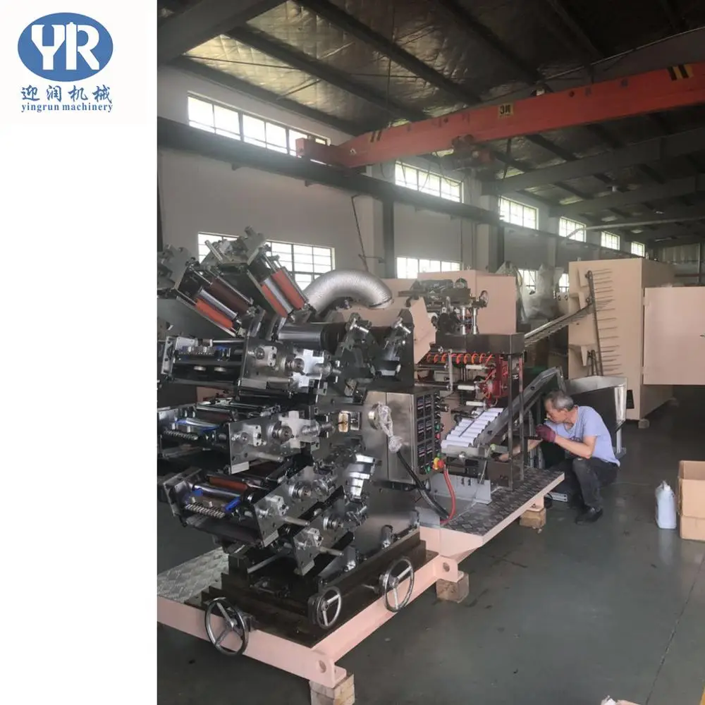
Eight-colors Printing & Varnish Machine, Drying Oven.
Specification
| 1 | Main power of printing machine | 7.5HP(5.5KW) |
| 2 | Main power of split system | 3HP(2.2KW) |
| 3 | Main power of drying oven | 3HP(2.2KW) |
| 4 | Main power of varnish, inlet, idler etc. | 90W+90W+90W=270W=0.27KW |
| 5 | UV drying system | 10KW |
| 6 | Static elimination system | 1.5KW |
| 7 | Drying oven heating system | 1.2KW*4=4.8KW |
Instructions for Printing System
1. Start-up steps
1.1. Turn on the main power switch
1.2. Open the door of control box,start the power switch then close the door and keep locked.
1.3. Press the “Power” button to keep the machine ready
1.4. Start the oven heater (four groups) to preheat, adjust the temperature in he control dashboard
1.5. Turn on the power of UV system and turn off the UV luminosity on the control box ( about 10 min for warm-up)
1.6. Start the motor of oven.
1.7. Add the glazing oil to the oil tanker,oil pan of the vanish system, then adjust the amount of the oil.
1.8. Wiping the ink on the wheel and transfer wheel.
1.9. AUTO Adjust the button of the UV system control panel, to 75%, 100% Auto.
1.10. Turn on the varnish system, electrostatic system, shaft motor, feeding motor and motion control system.
1.11. Put the material on the rack.
1.12. Turn on the electrostatic treatment system.
1.13. Screw the arrow of the governor (printing section) to the first half.
1.14. Start the printing motor.
1.15. The initial speed should be less than 70 pcs/min.
2. Oil fueling/change cycle
2.1. Ink roller axle and cam set, refuel once a week.
2.2. Plate wheel, ink seat, wheel wheel, motor gear, refuel every two weeks.
2.3. Rack disc, rear drive system, refuel once a month.
2.4. The light wheel system gear, refuel once a month
2.5. The splitter must be replaced oil for the first 1000 hours (about half a year) then replaced every year (using engine oil Mobil #632)
2.6. Others use butter #1
Data of Ink System
Name:
1. Inking system
2. Mix ink system
3. Supply ink system
4. Control cam of supply ink system
5. Ink tank
6. Make the ink uniform system
7. Ink volume adjustment bolt
8. Ink tank fixing bolt
9. Removable drive gear
Operating procedure:
1. The ink holder system is detachable and can easily clean the residual ink in the ink holder and manually adjust the ink.
2. Place the ink tank on the ink holder, lock the ink tank fixing bolts, and lock the leak-proof baffles on both sides, and pour the ink.
3. Start the motor of the printing system, or manually rotate the ink handwheel so that the ink can be taken up by the ink wheel, and adjust the ink amount bolt according to the amount of ink brought up to reach the initial required oil quantity.
4. The amount of ink supplied can also be rotated to the adjustment screw in the ink amount control cam group to change the position of the control cam contact, thereby achieving the purpose of adjusting the amount of ink supply.
5. The purpose of the ink roller is to uniformly apply the ink to the ink roller, which serves to improve the printing quality
6. The function of the ink-collecting wheel set is to make the ink-collecting effect appear. Therefore, the pressure adjustment between the ink-collecting wheel set and the ink-filling wheel has a great influence on the printing effect. The loading and unloading of the ink-collecting wheel is designed in a simple manner. Only the card pin needs to be pulled out, and the movable plate can be taken out for loading and unloading of the ink-removing wheel.
7. The adjustment method of the inking wheel set: firstly, the pressure between the inking wheel and the inking wheel, and the ink is transmitted to the inking wheel after the rotation.
8. When the ink of the inking wheel is even, the ink transfer operation can be performed.
9. The contact pressure between the inking wheel and the plate wheel is adjusted by the arc type, which can be controlled by the inking adjustment nut.
10. The function of the detachable transmission gear is that the unnecessary ink holder does not have to be separated from the machine itself, and only the transmission gear can be retracted.
Installation of Plate and Printing Blanket
Name:
1. Loading wheel screw
2. Radial phase adjustment worm
3. Printing rubber sheet fixing piece
4. Printing rubber plate axial adjustment screw
5. Axial phase adjustment nut
Installer:
1. Loosen the plate wheel fixing screw and remove the plate wheel to load and unload the printing rubber plate (you can also load and unload the printing rubber plate directly on the machine table)
2. The installation of the printing blanket and the square on the plate are the baseline, and the initial position of the wheel required for the pre-printing is confirmed.
3. Lock the two axial adjustment nuts and close the ink holder to adjust the contact pressure of the upper ink wheel to make the printing convex plate evenly inked.
4. When the printing style is copied on the wheel, the pressure between the wheel and the transfer wheel can be adjusted to make the color uniform.
5. Adjust the pattern error between the plates according to the color registration status displayed on the transfer wheel.
6. The radial color registration error is adjusted by the radial phase adjustment worm wheel and rod group.
7. The axial color registration error is adjusted by the axial phase adjustment nut on both sides of the wheel.
Data of Printing System Board
Description
1. Ersion wheel brake system: The main function is to counteract the inertial force. The contact pressure must be adjusted between the plate wheel and the transfer wheel, so the gear gap will be generated and the printing quality will be affected. Therefore, the brake system is installed to overcome this problem.
2. Adjustment of printing pressure: printing pressure directly affects printing quality, so that it is easy to adjust, so the principle of anti-threading is used to achieve the purpose of adjustment.
3. Transmission tracking system: The transmission of this machine mainly relies on the inverter to control the motor, and the speed control of the whole motor is controlled by the decoder. However, the control of the inverter uses the frequency to control the rotation speed, and its precision is rough, so it is reused. The proximity switch acts as a trigger and can loosen the flywheel screw to adjust the contact position of the printing wheel and the working mandrel
4. Transfer wheel brake system
4.1. Reducing damage to the motor during emergency braking
4.2. Reduce the damage of the transfer wheel gear and the wheel gear
5. Driven variable frequency motor: This motor is mainly used to track the speed of the main motor to achieve constant speed
6. Pneumatic control group: the main parts are:
6.1. Three-point combination: control the size of the air flow
6.2. Lubricate the cylinder: filter the water
6.3. Solenoid valve: switch to control air flow
7. Inverter: control the speed of the speed and the speed of each other, there is a difference between the active and the active
Data of Printing Machine Displacement Operation
Operation:
The way the printer is displaced is controlled by three handwheels located below the press machine.
1. Lateral adjustment wheel
2. Angle adjustment wheel
3. Longitudinal adjustment wheel
4. Transfer wheel manual adjustment handle
5. The base is only fixed by the swallowtail type , so its adjustment accuracy is very high.
Data of Printing machine splitter main control system
Name:
1. Splitter.
2. Friction system motor
3. Sense application cam
4. Inductive proximity switch
5. Pneumatic valve
6. Main drive sprocket
Function Description
1. Splitter: The main function is to change the continuous motion into intermittent motion to facilitate the operation of each system
2. Friction system motor: main movements include
2.1. Static elimination system
2.2. UV system
2.3. The core rods of the three systems, such as the glazing system, are rotated to achieve the purpose of eliminating static electricity, comprehensive UV drying and comprehensive glazing.
3. Inductive proximity switch: There are two proximity systems here. First, it is to control the setting of the speed and related position between the printing transfer rollers. Second, in order to control the positioning after the machine is stopped, the purpose is to determine the position at the next boot.
4. Pneumatic valve: The purpose is to control the outlet of the mandrel when the pipe is retracted, so that the hose is ejected to facilitate the operation of the retreating system.
5. Main drive chain: Driven by the main motor, it is also the main control of all drives.
Operation Data of the Inlet Pipe System
The system includes two parts: a feeding frame and an inlet pipe system.
1. Feed rack:Including(a)Round belt set(b)adjustable rack and adjustable baffle
1.1. The feeding frame can be arbitrarily adjusted within a limited range, so that hoses of various diameters can be applied. The feeding frame has two side guide plates and a baffle plate, and the function of the three plates is mainly to enable the hose to achieve the function of the pipe in a certain range.
1.2. Conveyor belt set: There is a 90W-1/20 adjustable speed reduction small motor in the organization. Its function is to effectively introduce the hose into the inlet pipe system, and the speed adjustment function is to make the feeding speed of the hose The working speed of the host is matched
2. Inlet system: the cycle of its operation is driven by a link according to the speed of the main table, so it can be consistent with the speed of the main table, and the spring and a micro switch are added after the push rod, which is free from the pipe. Automatic shutdown when not normal to maintain the mechanism from injury
Data of Static Elimination and Loading Glazing Detection System
Name:
1. Static elimination rod
2. Static elimination rod fixing group
3. Detection photoelectric group
4. Electrostatic strength control box
Description:
1. Static elimination system: The static elimination rod removes the static electricity generated by the hose during processing, so that the printing ink can be determined to adhere to the plastic hose.
2. Detection of photoelectric system: The detection system mainly detects whether there is a hose on the mandrel. If there is no hose, the glazing system will immediately detach when the mandrel passes through the glazing system to ensure the drying of the mandrel, smooth the operation of the machine and keep the inside of the hose clean.
3. Static Disappearance Strength Control Box: Its main function is to control the strength of static elimination bar current.
Data of UV Drying System
Principle description:
1. The working principle of the UV drying system is to use the intense ultraviolet light to pass through the concentrating device and the rotation of the hose itself to make the printing ink on the surface of the hose dry quickly.
2. When UV drying is used, strong light will generate high temperature, so it is necessary to install an exhaust windmill so that the temperature of the working area is not too high. If the temperature is too high, the host protection system will automatically start and stop automatically.
3. The design of the lamp tube requires a high-powered light, so the two-stage start mode is adopted.
Instructions:
1. Start the power switch in the control box. After 3~5 minutes, start the 50% switch. At this point, the light of the system will be slowly illuminated. At this point, you have to wait another 10 minutes or so to start the last 75%-100% switch.
2. When the entire machine is started, the AUTO/MANUAL button in the UV drying system control box is pressed to the automatic position and connected to the host. When the host stops, the system will automatically turn off the lights to protect the life of the lamp and control box, and vice versa.
3. The cooling windmill is controlled by the temperature sensing, so when the temperature of the working area is higher than the set temperature, the windmill is started to dissipate heat.
4. When the host is stopped, the shutdown of the control system of the drying system cannot be turned off at the same time. The two switches that control the light must be turned off first. At this time, the cooling windmill will continue to operate until it is lower than the set temperature (about 10 minutes).
Data of the Glazing System
Name:
1. Detachable pneumatic cylinder
2. Drive motor
3. Vertical adjustment wheel set
4. Up and down adjustment wheel set
5. Pressure adjustment bolts
6. Heart stick retracting air outlet controller
7. Action rubber wheel
8. Oiling iron wheel
9. Oil roller
10. Active axis
Data of Transmission Step
1. The main drive of the glazing machine is driven by a 90W small-shaped gear motor with adjustable speed. Therefore, the mechanism can be adjusted according to the speed of the host to optimize the glazing quality.
2. The mechanism is connected with the photoelectric switch in the inlet pipe system. When the photoelectric switch does not sense the presence of the hose, the message will be transmitted to the main control console, and then transmitted to the solenoid valve for controlling the release cylinder, and will be glazed at an appropriate time. The wheel is disengaged to keep the working mandrel clean for production
Operating procedure:
1. Secure the oil sump to the fixing pin below the system.
2. Load the varnish in the oil bath.
3. Adjust the lower pressure adjusting bolt so that the upper oil tank and the rubberizing wheel are engaged, and the contact pressure of each part is uniform
4. Adjust the upper pressure adjusting bolt to make the upper oil tank match the oil tanker and adjust the pressure between the variable wheel Uniform force.
5. Start the upper wheel motor, observe the oil evenly and thick, adjust the pressure adjustment bolt according to the result, to achieve its initial effect
6. Load the hose on the working mandrel, test the uniformity and thickness of the oil, and observe the position of the glazing
7. Adjust the (upper, lower and vertical, horizontal) to the best position according to the results obtained, in order to achieve the best work quality
Data of Intermittent Transition Continuous Motion Control System
Name:
1. Speed controller
2. Conversion exercise mode group
3. Safe shutdown system
Description:
1. The function of this mechanism is to change the intermittent movement into continuous movement to match the operation of the oven.
2. The transmission between the main unit and the oven is controlled by two separate inverter motors. Therefore, the linkage between the two machines is connected to the PLC (variable program control group) of the main control box by using each other's inverter and decoder, and then proportional. Controller processing to achieve synchronized speed output
3. Since the chain length of the oven is very considerable, the control of synchronization is difficult. Therefore, a set of speed controllers is added to the conversion motion mode group.
4. Speed controller: The speed controller is mainly composed of a movable proximity switch mount and two proximity switches.
5. Conversion movement mode idler group: The conversion movement mode is composed of four sets of fixed idler sets and a set of movable idler sets.
6. Safety shutdown system: The safety shutdown system mainly protects the machine itself, so that it can be shut down immediately under improper operation to ensure the mechanical life.
7. Mode of action: When the main body transfers the movement to the system, the conversion idler group facilitates the use of its own active wheel set to retain the excess portion and release the amount of activity required for the oven. However, although the speeds of the two sets of motors (main drive motor and oven motor) are tracked by the decoder, the speeds are not consistent, and the gap between the chains must not be ignored. Therefore, when the idler gear hits the upper proximity switch, the oven drive motor is forced to reduce the speed. Conversely, when the idler set touches the lower proximity switch, the oven drive motor is again accelerated. The safety shutdown system is set to prevent the inertia of the machine from being too fast or too slow.
Principle of Oven Cooling and Withdrawal System
Cooling system description
1. The cooling system is placed in the last stage of the oven. Its main destination is to cool the hot-baked hose in a short time to make the glazing effect perfect.
2. The cooling system is divided into two parts:
A. Cooling cycle fan cooling, the main function is to cool the hose due to strong cold.
B. The fan is usually cooled and placed at the end of the oven. Its function is to cool the hose again.
Automatic withdrawal system:
1. His machine adopts the method of blow-out type, mainly uses the micro switch to control the air blowing time of the air duct.
2. When the mandrel touches the micro switch, the gas valve is activated and the hose is blown out.
Data of Oven Heating and Transmission Principle
Heating instructions
The heating system can be divided into four parts
1. The main function of the heating tube is also heating
2. The incubator is mainly used to keep the heat generated by the heater in the box.
3. The air supply motor sends the heat energy in the incubator to the oven through the heat preservation air duct, and then recycles the remaining heat energy in the oven.
4. The temperature sensor controls the temperature in the oven
Drive description
1. The main drive is composed of a 3HP inverter motor that is transmitted to a 1/40 reducer.
2. Synchronized with the host by a set of helical gears.
3. Finally, the kinetic energy is transmitted to each set of bevel gears connected to it through a transmission shaft to achieve the purpose of the sprocket transmission in the oven.
Похожие товары

Печатная машина с 4 цветами
US $19000


CF4PYNP-470 Автоматическая офсетная печатная машина NCR
US $23000-$40000
