L & R Варистор оксида цинка для
- Категория: Резисторы >>>
- Поставщик: Yueqing,L&r,Imp&exp,Co.,Ltd.
Поделиться:
Описание и отзывы
Трекер стоимости
| Месяц | Минимальная цена | Макс. стоимость |
|---|---|---|
| Aug-15-2025 | 1.51 $* | 1.66 $* |
| Jul-15-2025 | 1.67 $* | 1.49 $* |
| Jun-15-2025 | 1.64 $* | 1.28 $* |
| May-15-2025 | 1.45 $* | 1.42 $* |
| Apr-15-2025 | 1.32 $* | 1.24 $* |
| Mar-15-2025 | 1.97 $* | 1.62 $* |
| Feb-15-2025 | 1.17 $* | 1.6 $* |
| Jan-15-2025 | 1.66 $* | 1.41 $* |
Характеристики
Advantage

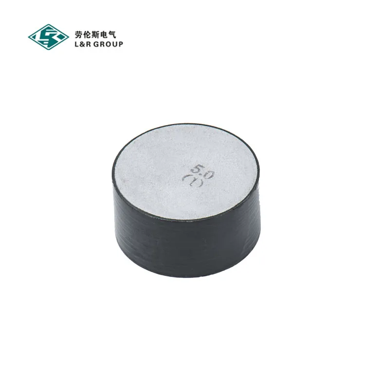
Product Description
L&R zinc oxide varistor elements, developed by L&R Corporationover many years of research, are composed of a
speally formulated compoundof zinc oxide and small amounts of other selectedmetal oxides. After a series of process,
these ingredients result in polycristalline cerarruc. L&Rzinc oxide varistor elements are testedin accordance with the
latest standard IEC 60099 -4 for metal oxidearresters, and consistently maintain astable characteristic. Accelerated
Life tests show that arrester losses willnot increase during an arrester 'sservice life at a maximum continuous operating
voltage, Electric testsare a very critical part of zinc oxide varistorelements production. Asample is selected from each
batch of varistor elements and subjected to an accelerated life test, If the test is successful each varistor elementreceives
a two long- duration test, a discharge current test at 2.5kA,5kA, 10kA and 20kA, and a reference voltage test to sortthe
elements.
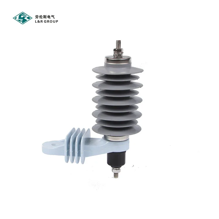
Application
1.Arrester use under oil-immersed transformer
2.GIS arrester
3.Railway arrester(DC substation use,mount on rolling stock)
4.Cable sheath protection arrester
5.Low voltage surge absorber
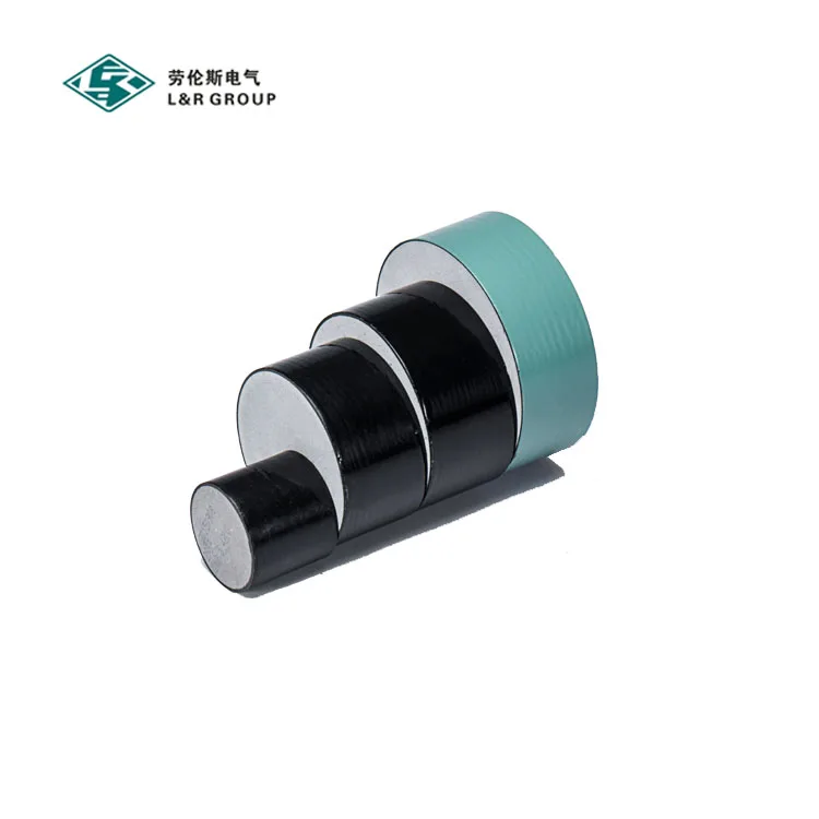
| Specification of Metal Oxide Varistors | |||||||||
| Used For 5KA Distribution | |||||||||
| Specification | Diameter | Thickness | D.C. reference voltage (U1mA) | Leakage current under 75%U1mA | Max. ratio of residual voltage (8/20us) | Current impulse withstand capability | Recommended rated voltage | Recommended continuous operating voltage | |
| 4/10us | 2ms | ||||||||
| mm | mm | kV | uA | at 5kA | kA | A | kV | kV | |
| MOV28×20 | 28±0.5 | 20±0.5 | 4.0-4.8 | <10 | 1.81 | 65 | 120 | 3 | 2.4 |
| MOV28×24 | 28±0.5 | 24±0.5 | 5.0-5.8 | <10 | 1.81 | 65 | 120 | 3.6 | 2.88 |
| MOV28×30 | 28±0.5 | 30±0.5 | 6.2-7.0 | <10 | 1.81 | 65 | 120 | 4.5 | 3.6 |
| MOV30×3 | 30±0.5 | 3.0±0.5 | 0.6-0.8 | <10 | 1.78 | 65 | 120 | 0.28 | 0.22 |
| MOV30×6 | 30±0.5 | 6.0±0.5 | 1.2-1.6 | <10 | 1.78 | 65 | 120 | 0.5 | 0.4 |
| MOV30×20 | 30±0.5 | 20±0.5 | 4.0-4.8 | <10 | 1.78 | 65 | 150 | 3 | 2.4 |
| MOV30×24 | 30±0.5 | 24±0.5 | 5.0-5.8 | <10 | 1.78 | 65 | 150 | 3.6 | 2.88 |
| MOV30×30 | 30±0.5 | 30±0.5 | 6.2-7.0 | <10 | 1.78 | 65 | 150 | 4.5 | 3.6 |
| MOV32×20 | 32±0.5 | 20±0.5 | 4.0-4.8 | <10 | 1.75 | 70 | 200 | 3 | 2.4 |
| MOV32×24 | 32±0.5 | 24±0.5 | 5.0-5.8 | <10 | 1.75 | 70 | 200 | 3.6 | 2.88 |
| MOV32×30 | 32±0.5 | 30±0.5 | 6.2-7.0 | <10 | 1.75 | 70 | 200 | 4.5 | 3.6 |
| MOV35×20 | 35±0.5 | 20±0.5 | 4.0-4.8 | <10 | 1.72 | 75 | 250 | 3 | 2.4 |
| MOV35×24 | 35±0.5 | 24±0.5 | 5.0-5.8 | <10 | 1.72 | 75 | 250 | 3.6 | 2.88 |
| MOV35×30 | 35±0.5 | 30±0.5 | 6.2-7.0 | <10 | 1.72 | 75 | 250 | 4.5 | 3.6 |
| Used for 10kA distribution and station/ substation of class 1, IEC | |||||||||
| Specification | Diameter | Thickness | D.C. reference voltage (U1mA) | Leakage current under 75%U1mA | Max. ratio of residual voltage (8/20us) | Current impulse withstand capability | Recommended rated voltage | Recommended continuous operating voltage | |
| 4/10us | 2ms | ||||||||
| mm | mm | kV | uA | at 10kA | kA | A | kV | kV | |
| MOV37×20 | 37±0.5 | 20±0.5 | 4.0-4.8 | <10 | 1.8 | 100 | 300 | 3 | 2.4 |
| MOV37×24 | 37±0.5 | 24±0.5 | 5.0-5.8 | <10 | 1.8 | 100 | 300 | 3.6 | 2.88 |
| MOV37×30 | 37±0.5 | 30±0.5 | 6.2-7.0 | <10 | 1.8 | 100 | 300 | 4.5 | 3.6 |
| MOV42×20 | 42±0.5 | 20±0.5 | 4.0-4.8 | <10 | 1.77 | 100 | 400 | 3 | 2.4 |
| MOV42×24 | 42±0.5 | 24±0.5 | 5.0-5.8 | <10 | 1.77 | 100 | 400 | 3.6 | 2.88 |
| MOV42×30 | 42±0.5 | 30±0.5 | 6.2-7.0 | <10 | 1.77 | 100 | 400 | 4.5 | 3.6 |
| Used for 10kA power station/ substation of class 2, IEC | |||||||||
| Specification | Diameter | Thickness | D.C. reference voltage (U1mA) | Leakage current under 75%U1mA | Max. ratio of residual voltage (8/20us) | Current impulse withstand capability | Recommended rated voltage | Recommended continuous operating voltage | |
| 4/10us | 2ms | ||||||||
| mm | mm | kV | uA | at 10kA | kA | A | kV | kV | |
| MOV48×20 | 48±0.5 | 20±0.5 | 4.0-4.8 | <15 | 1.75 | 100 | 600 | 3 | 2.4 |
| MOV48×24 | 48±0.5 | 24±0.5 | 5.0-5.8 | <15 | 1.75 | 100 | 600 | 3.6 | 2.88 |
| MOV48×30 | 48±0.5 | 30±0.5 | 6.2-7.0 | <15 | 1.75 | 100 | 600 | 4.5 | 3.6 |
| MOV52×20 | 52±0.5 | 20±0.5 | 4.0-4.8 | <15 | 1.73 | 100 | 700 | 3 | 2.4 |
| MOV52×24 | 52±0.5 | 24±0.5 | 5.0-5.8 | <15 | 1.73 | 100 | 700 | 3.6 | 2.88 |
| MOV52×30 | 52±0.5 | 30±0.5 | 6.2-7.0 | <15 | 1.73 | 100 | 700 | 4.5 | 3.6 |
| MOV60×20 | 60±0.5 | 20±0.5 | 4.0-4.8 | <15 | 1.68 | 100 | 900 | 3 | 2.4 |
| MOV60×22.5 | 60±0.5 | 22.5±0.5 | 4.5-5.1 | <15 | 1.68 | 100 | 900 | 3 | 2.4 |
| MOV60×30 | 60±0.5 | 30±0.5 | 6.2-7.0 | <15 | 1.68 | 100 | 900 | 4.5 | 3.6 |
| Used for 10kA power station/ substation of class 3, IEC | |||||||||
| Specification | Diameter | Thickness | D.C. reference voltage (U1mA) | Leakage current under 75%U1mA | Max. ratio of residual voltage (8/20us) | Current impulse withstand capability | Recommended rated voltage | Recommended continuous operating voltage | |
| 4/10us | 2ms | ||||||||
| mm | mm | kV | uA | at 10kA | kA | A | kV | kV | |
| MOV64×30 | 64±0.5 | 30±0.5 | 6.2-7.0 | <15 | 1.67 | 100 | 1000 | 4.5 | 3.6 |
| MOV71×22.5 | 71±0.5 | 22.5±0.5 | 4.5-5.1 | <15 | 1.65 | 100 | 1300 | 3 | 2.4 |
| Used for 10kA power station/ substation of class 4, IEC | |||||||||
| Specification | Diameter | Thickness | D.C. reference voltage (U1mA) | Leakage current under 75%U1mA | Max. ratio of residual voltage (8/20us) | Current impulse withstand capability | Recommended rated voltage | Recommended continuous operating voltage | |
| 4/10us | 2ms | ||||||||
| mm | mm | kV | uA | at 10kA | kA | A | kV | kV | |
| MOV115/42x22.5 | 115/42±0.5 | 22.5±0.5 | 4.5-5.1 | <30 | 1.59 | 100 | 2000 | 3 | 2.4 |
| Used for 20kA power station/ substation of class 5, IEC | |||||||||
| Specification | Diameter | Thickness | D.C. reference voltage (U1mA) | Leakage current under 75%U1mA | Max. ratio of residual voltage (8/20us) | Current impulse withstand capability | Recommended rated voltage | Recommended continuous operating voltage | |
| 4/10us | 2ms | ||||||||
| mm | mm | kV | uA | at 20kA | kA | A | kV | kV | |
| MOV138/52x22.5 | 138/52±0.5 | 22.5±0.5 | 4.5-5.1 | <30 | 1.65 | 100 | 2500 | 3 | 2.4 |
SA navigation
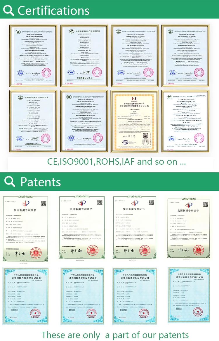
Certifications
Packaging

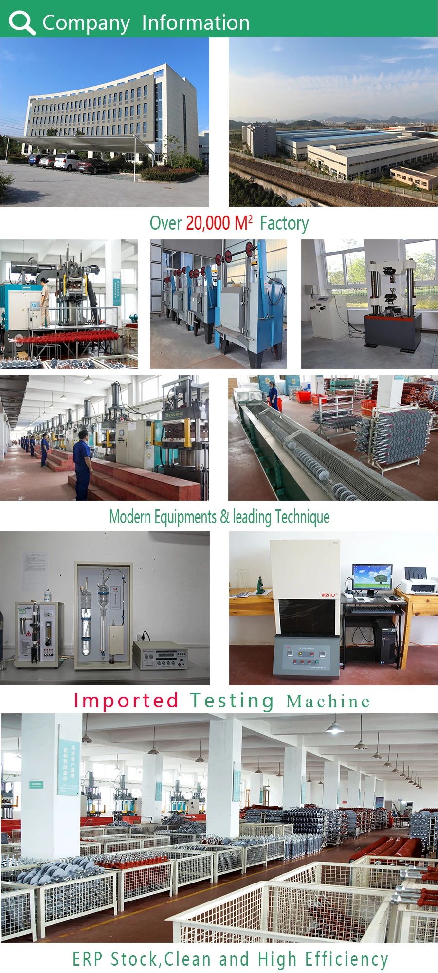
Company Information
Customer

Public