
Вешалка для гальванического покрытия Feiyide
US $50.00-$400.00
Поделиться:
| Месяц | Минимальная цена | Макс. стоимость |
|---|---|---|
| Sep-17-2025 | 0.91 $* | 0.67 $* |
| Aug-17-2025 | 0.46 $* | 0.18 $* |
| Jul-17-2025 | 0.69 $* | 0.63 $* |
| Jun-17-2025 | 0.2 $* | 0.39 $* |
| May-17-2025 | 0.93 $* | 0.97 $* |
| Apr-17-2025 | 0.85 $* | 0.48 $* |
| Mar-17-2025 | 0.37 $* | 0.28 $* |
| Feb-17-2025 | 0.79 $* | 0.56 $* |
| Jan-17-2025 | 0.24 $* | 0.23 $* |
WUXI FEM MACHINERY SCIENCE &TECHNOLOGY CO.,LTD

1.The Description Of Brass Plating Machine
Copper plated steel wire is core technique of steel cord production. And its importance is proved by the naming that the name of the technique is Installation of Steel Cord. Before ISC, the wire rod with 5.5mm in diameter turns to 1mm in diameter by coarse drawing and intermediate drawing. The machine used in lager push include (OLW+JUBITER B, BA,BAZ) & (JUPITER C,CA,CAZ,CAA,CAB).we will offer a detailed introductions for these machine in the training for coarse drawing. According to the requirement of finished product of steel cord for breaking force, the wire will reach the suitable tensile strength by ISC For the poor adhesive between steel and rubber, we plate a very thin layer of brass (Cu+Zn) to the surface of wire, through ISC.
The objective of ISC, Meet the requirements of wet drawing technique, by recovering the malleability of wire. To provide ideal metallographic structures to ensure the work hardening through wet drawing process. To ensure single wire to reach the needed tensile strength after wet drawing To achieve this by two steps: Austenitizing (Furnace) The treatment of isothermal quenching (WAP, FB, Lead bath) We use the wire rod with carbon content more than 0.70 percent as the raw materials, so that our finished products will have a high tensile strength.
2.The Process Of Production Technology

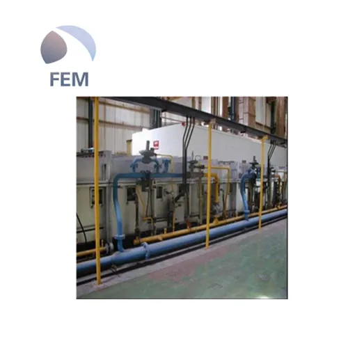
1.Copper plating line overview and technique introduction
2 Auto pay-off unit
3 Condition bath
4 Heating furnace
5 WAP bath 6
Cooling bath after Patenting
7 NaOH bath
8 Rinsing bath after NaOH
9 Acid washing bath
10 Rinsing bath after acid washing
11 Copper plating bath
12 Zinc plating bath
13 MF (diffusion)
14 Water cooling after MF
15 Acid washing and rinsing
16 Soap dipping
17 Dryer (Optional)
18 Take-up
3. Some Process Introduction
The minimum water level in tank is controlled by float switch. Adjust the switching point of the float switch and keep it the same as the working liquid level. If in production the liquid level is lower than working liquid level, float switch will open pneumatic valve, fresh water can be added in to tank until reaches to the minimum water level. Make sure in production the drain valves of the cooling part of the tank are completely closed. Make sure water supply valve is equipped prior to the pneumatic water supply valve and completely open in production. Make sure in production the by-pass water supply valves are completely closed, only when you add water into tank you need to open it manually. The temperature of tank is controlled by external heat-exchanger, when the temperature of the second part is over high, the circulating pump starts. Open valves at the front and back side of the heat-exchanger all the time during the production. There is one temperature reading meter which can sense temperature of the second part. Normally, there is only one pump of the cooling part works. Wire temperature is cooled to ± 120℃, in this way wire can heat acid solution in the H3PO4 tank. If the temperature of the H3PO4 tank is over high, PT100 in the tank will send a signal to start the screw pump in second part to make wire further cooled.
Acid continuous loop strengthen pickling effect. There is a ceramic clean liquid lever behind each overflow plate to prevent the outside acid into the next slot. Acid is recycled into groove, each brush liquid lever has its own cyclone remove the droplets in the air. Phosphoric acid is added to the final of a controlled by conductivity meter, Concentrated phosphoric acid added by pneumatic diaphragm pump and the add quantity completed by manual adjustment to control the speed of the pump. Water rising (6 tubs) The steel wire through the six series water rinse tank The next flush of rinse water can be used in the front rinse tank In each water rinse tank, the water is overflow from the tank through a vertical screw pump, Then it into a wire through the overflow of the plate. Water adds to the last rinse tank and according to flush the tank flow. When it stops ,the water discharge to the wastewater treatment plant. Water is recycled to the phosphate tank emissions when it works. There is an automatic valve in the discharge tube. During the production line running ,the valve is closed when the pump stop.
There is a ceramic clean liquid lever behind each overflow rate. To prevent from the previous with the water into the next slot in the slot, each brush liquid lever has its own cyclone to remove the water droplets in the air.
Each pump and fan has a maintenance switch, disconnect the power of the pump or fan when maintenance Pump test button The main operating: Select the pump needs to be tested and then press the test pump. To detect and stop reason There are three tubs with a hot relay each. The auxiliary contact hot relay series connection input to the PLC. There will be alarm information display when any relay action. Temperature can be read from the production line operation board Conductivity meter used to measure the electrical of phosphorus, on the operation board production line can also be electrical conductivity of the set up and read. Water washing There are six tubs with a hat relay each. The auxiliary contact hot relay series connection input to the PLC. There will be alarm information display when any relay action. Thermal protection of contact signal input PLC with a suction fan
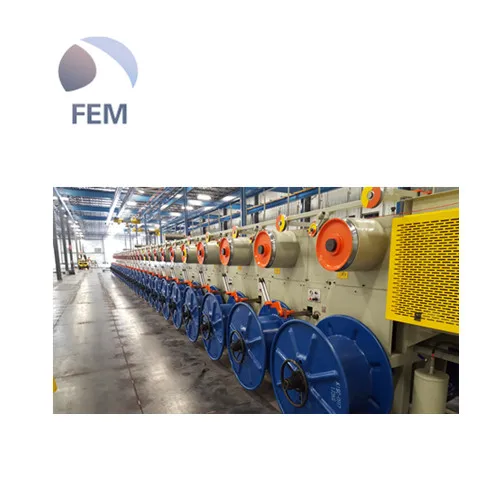
4. Take-up
Take-up part is composed of four independent framework, arranged in a column, the upper is equipped with 56 the traction wheels with a diameter of 350 mm. Traction wheel is driven by an independent motor drive, the motor driven by four frequency transducer group, each transducer with the same parameters, to ensure uniform speed. Ramses device on both sides have an additional auxiliary traction wheel and h wheel shaft, making production in high-speed. H wheel is driven by an independent constant torque motor. The motor driven by two transducer group. Wheel speed can be on the basis of the reference frequency by adjusting the output voltage frequency transducer, to ensure the case of a certain amount of tension and traction wheel speed is consistent, Each wheel can start and stop independently. H wheel spindle is equipped with a fast locking system for rapid loading and unloading wheel, and Ramses machine end also is equipped with two waste wheel, one side each, used for low speed winding wire in production line. Each pair of traction motors and wheel motors are controlled by a local control box. The wheel motor thermal protection circuit breaker through a connecting rod connected to the door of the control box, used as a wheel of the switch. Control box door is equipped with a button to change the direction of the system. Work on each side, all equipped with a rope so that in an emergency stop switch to stop the line.
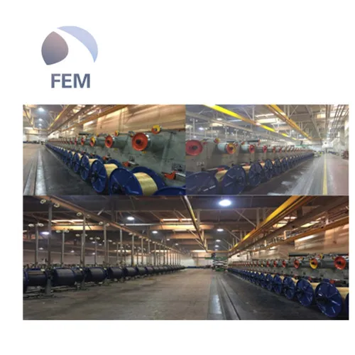
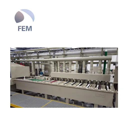
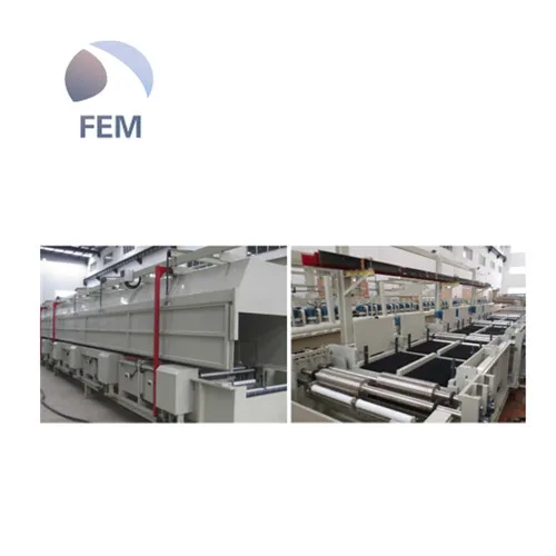
5. Pictures Of Brass Plating Lines


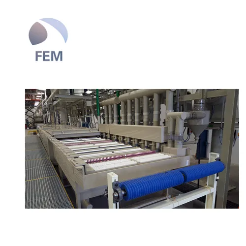
6. Our Workshop


Данные ресурс не является интернет-магазином, а лишь содержит ссылки на международную торговую площадку Alibaba.com


