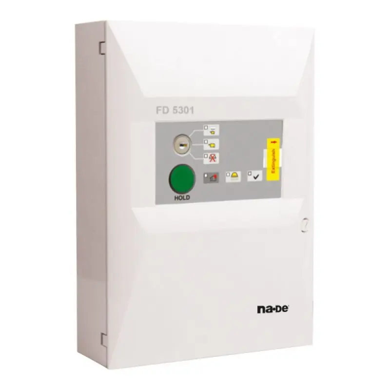
IntroductionModule FD5301 is designed to operate together with Fire Extinguishing Control Panel FS5200E.
The device allows remote access on a
part of the panel controlling components and indicators, related with the extinguishing process.
The remotely controlled panel basic functions are:
- Manual activation of Extinguishing;
- Selecting the Control Panel Modes of operation – Manual/Auto mode or only Manual mode
- Disable Extinguishing
- Hold Extinguishing
The following indicators are duplex controlled:
- Fire Condition 2nd Stage
- Disable Extinguishing
- Gas Released
- Manual Mode
- Manual/Auto Mode
Technical Data
Indication - LED
Power Supply - 28 V DC of the Control Panel or an autonomous power supply,
compatible with the EN54-4 requirements
Dimensions - 313x218x85 mm
Weight - 1,125 kg
Complete Set
- Module FD5301 - 1 pc
- Key switch - 2 pcs
- Instruction Manual - 1 pc
- Transport package - 1 pc
- Safety sticker for fixing the fuse of button Manual Release - 3 pcs
Labour Protection Requirements
Personnel, involved in installation and maintenance of the module must know the structure and operation of the equipment and the basic safety requirements.
Faults must be removed after disconnecting the power supply.
The module can be installed in premises with a normal fire hazard under the current standards and regulations
Installation and preparing for operation
5.1. Fixing the module
• Unpack the device
• Open the module after unlocking.To unlock use a coin, place the coin into the slot of the plastic door lock and rotate 90 counterclockwise
• Mount the dowels for fixing on the proper place
• Fix the module to the dowels through the three openings of the box
• Bore the holes at the top of the box, on the vacant places and pass the cables
5.2. Terminal Bus
All signal and power cables are connected using the terminals, mounted on the printed-circuit board.
• “Manual Release” – The output is used for manual activation of the extinguishing process in the control panel.
• “Mode Select” –The output is used for selection of the operating mode in the Control Panel.
• “Hold” – The output is used to hold, (delay) the extinguishing process in the Control Panel.
• “On/Off Exting” – The output is used for releasing a signal to the Control Panel from a switcher for disabling the extinguishing process.
• “Rele Fire” – Terminals for connection with “Rel 2ST” of the Control panel (output of the panel, relay, potential-free, the line status is not controlled. It is used to control the devices when the Control Panel has entered Fire Condition 2nd Stage). • “+28V” –Terminals for power supplying the device from the control panel or external power supply.
• “OK1” – Terminals for control of the FD5301 indication, triggered on activated Control Panel open collector /GND on active panel open collector, +28V on inactive panel open collector/. The input is active when the Control panel
has registered a leak of extinguishing agent.
• “OK2” – Terminals for control of the FD5301 indication, triggered on activated Control Panel open collector /GND on active panel open collector, +28V on inactive panel open collector/. The input is active when the Control Panel has Disabled Extinguishing Mode.
• “OK3” – Terminals for control of the FD5301 indication, triggered on activated Control Panel open collector /GND on active panel open collector, +28V on inactive panel open collector/. The input is active, when the Control Panel is in Manual Mode.
The scheme of connecting module FD5301 to FS5200E is given.
Note1: From the Control Panel FS5200E menu ''System Functions/SetUp/Input-outputs/Input Hold” the activity of the input “Hold” must be changed from ''Open” to ''Closed”.
Note2: Contacts of the relay "Rel 2ST" in the extinguishing panel must be configured by the jumper as "normally open''.
6. Indication
Indicator “Power supply” - Module is power supplied (pos.8, fig.4)
Common Indicator “Fire Condition 2nd Stage ” – continuous red light (pos.6, fig.4)
Indicator “Manual Mode” – continuous yellow light (pos.4, fig.4)
Indicator “Manual-Auto Mode” – continuous yellow light (pos.3, fig.4)
Indicator “Disable Extinguishing” – continuous yellow light (pos.5, fig.4)
Indicator “Low Pressure” – fault condition Low pressure into the Extinguishing installation - continuous yellow light (pos.7, fig.4)
7. Using the buttons
7.1. Mode selection:
• Manual/Auto – Turns the secret key switch in position “Manual/Auto mode”. The LED is on (pos.3, fig.4)
• Manual Mode - Turns the secret key switch in position “Manual”. The LED is on (pos.4, fig.4).
7.2. Using the buttons in case of Fire Condition:
• Disable Extinguishing - Turns the secret key switch in position “Disable Extinguishing. The LED is on (pos.5, fig.4)
• Hold Extinguishing – press button “HOLD”. The evacuation time is extended (pos.1, fig.4)
• Forced Extinguishing activation:
- tear-off the protective sticker
- slide the protective plate until discovering button “Extinguish”
- press the button to activate the extinguishing (pos.9, fig.4)
8. Conditions of transport, storage and operation
8.1. Operation and Storage
The module is to be used and kept in closed premises under the following boundary conditions:
• Temperature range
-storage temperature range 5°C to 35°C
-transport temperature range minus 10°C to 50°C
-operating temperature range minus 5°C to 40°C
• Relative humidity resistance
- storage up to 80%
- operation up to 93%
8.2. Transport
The module is to be transported in closed vehicles, in factory packaging and at the mentioned above weather conditions.
9. Warranty
The manufacturer – guarantees that the device is in compliance with EN 54-2:1997, A1:2000, BDS EN 54- 4:1997, A1:2002, A2:2006 and EN 12094-1: 2003. The warrant period is 24 months from the date of the purchase providing that:
- The conditions of the storage and transport are observed
- Start-up is gone by authorized by the company - manufacturer person
- The operating requirements of the Instruction manual here in have been observed