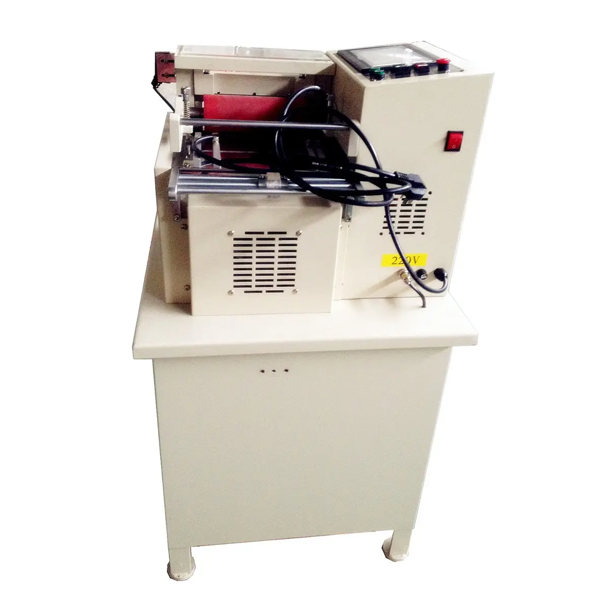
Автоматическая машина для резки резиновых лент
US $1500-$4500
Поделиться:
| Месяц | Минимальная цена | Макс. стоимость |
|---|---|---|
| Sep-15-2025 | 0.47 $* | 0.39 $* |
| Aug-15-2025 | 0.91 $* | 0.80 $* |
| Jul-15-2025 | 0.19 $* | 0.15 $* |
| Jun-15-2025 | 0.50 $* | 0.71 $* |
| May-15-2025 | 0.30 $* | 0.15 $* |
| Apr-15-2025 | 0.58 $* | 0.54 $* |
| Mar-15-2025 | 0.95 $* | 0.45 $* |
| Feb-15-2025 | 0.8 $* | 0.64 $* |
| Jan-15-2025 | 0.48 $* | 0.79 $* |
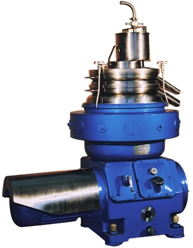
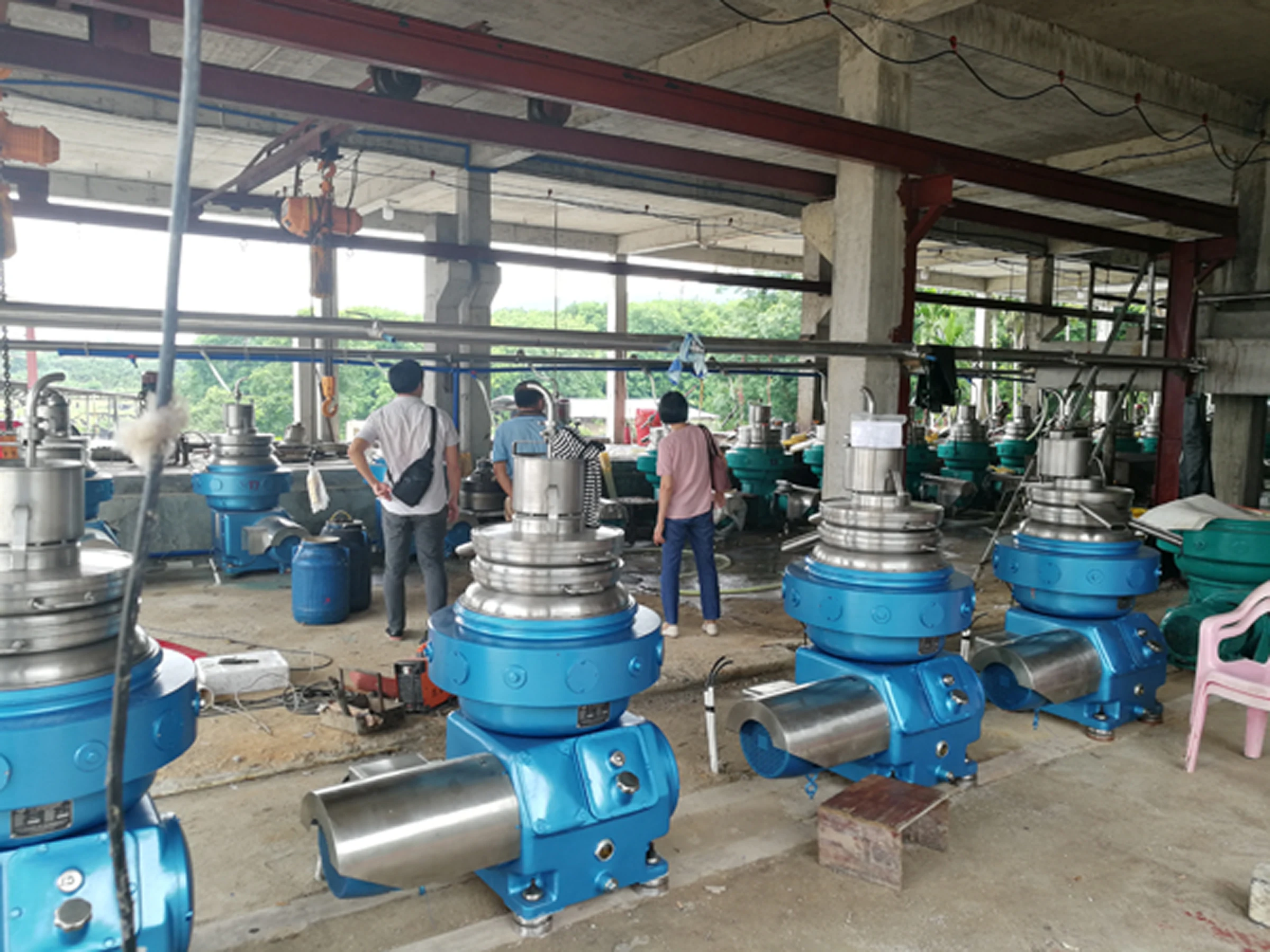
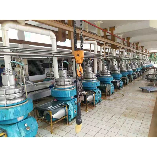
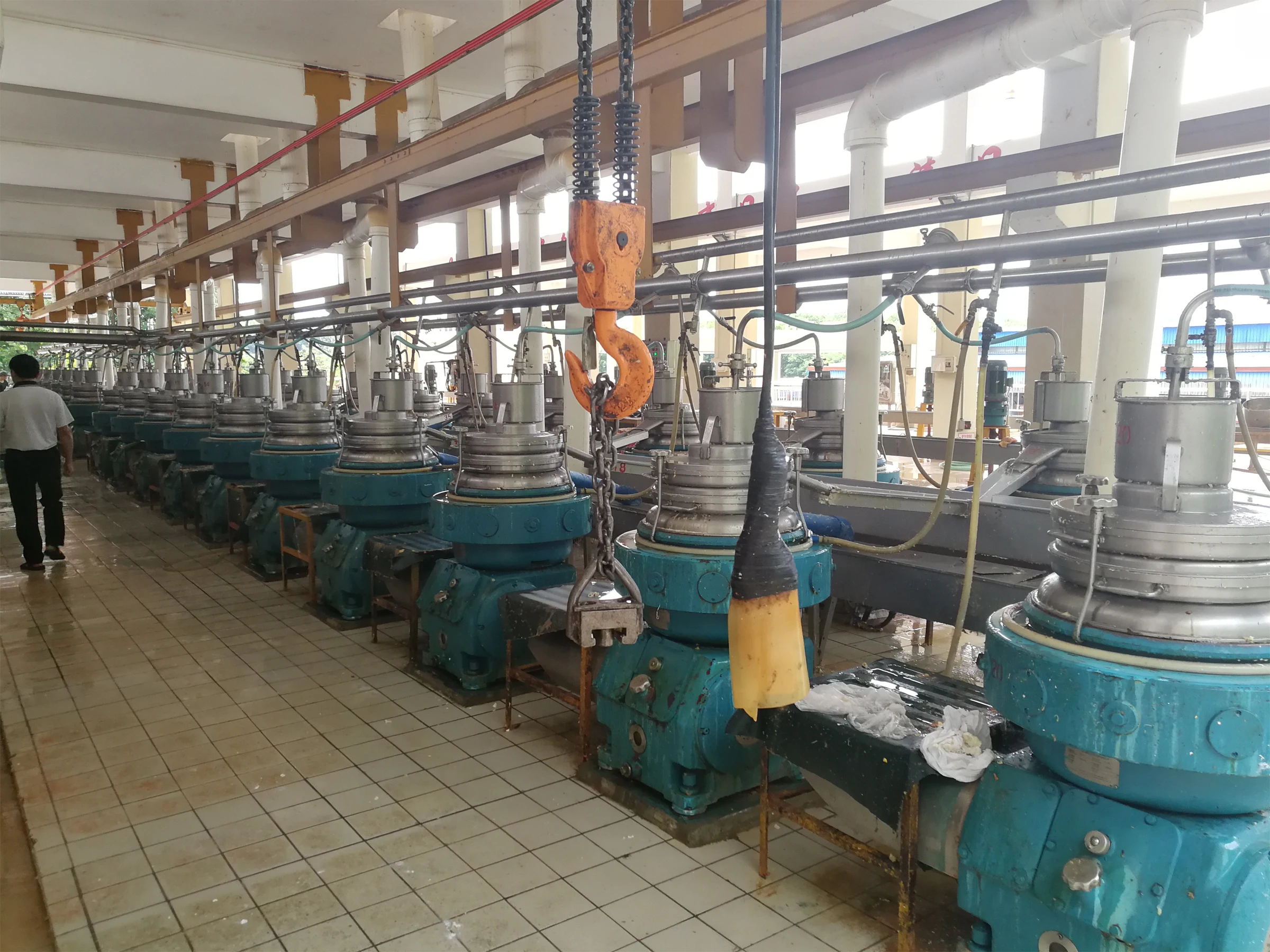
DR-400E, DRR480 Latex Separator

1. Application and characteristics of the machine
DR-400E, DRR480 Latex separator is a high-speed settling disc separator for manual slag removal, which is specially used for concentrating latex and clarifying impurities in latex. The bowl material of the machine is made of high-strength corrosion-resistant stainless steel. Each bowl has undergone strict flaw detection and mechanical performance test. The strength of the bowl is safe and reliable. The bowl and internal components have undergone accurate dynamic balance and stable operation. It has the advantages of tight structure, convenient operation, simple maintenance and good separation effect.


2. Main technical parameters
Main parameter | DR400-E | DRR480 |
Bowl diameter | Inner diameter 400 mm Out diameter 460 mm | Inner diameter 400 mm Out diameter 460 mm |
Max. speed | 7250 r/min | 7250 r/min |
Disc | 115+5 Pcs Disk spacing : 0.5 mm | 130 pcs Disk spacing: 0.5 mm |
Max. Processing capacity | 300~600 L/h (depending on material condition) | 350~700 L/h (depending on material condition) |
Separating factor | 11770 | 11770 |
Adjust pipe length | 9.5, 9.8, 10, 10.5, 11, 11.25, 11.5, 11.75,12,12.5,13,13.5,14,14.5,15 | |
Adjust pipe diameter | 11.5, 10.5, 9, 8.75, 8 | |
Drive motor power | Y160M-4B 11 KW, 1460 Rpm | Y160L-4-TH-B5, 15 KW, 1460 Rpm |
Starting time | 5-10 min | 5-10 min |
Stopping time | 4 min (adjustable) | 4 min (adjustable) |
Overall dimension (L × w × h) | 1270 × 910 × 1700 mm | 1270 × 910 × 1700 mm |
Weight | 1100 Kgs | 1150 kgs |
3. Separation principle

As shown in the right figure, the fresh latex flows into the regulating pipe (see Figure 1) from the feeding pipe device (1-0), and the liquid level in the cylinder is kept constant by the float device (2-0). The fresh latex flows into the center of the bowl (7-0) by gravity. Under the effect of centrifugal force field, the light phase (i.e. concentrated latex) is discharged along the outer surface of the disc through the small hole on the top of the bowl cover at the light phase outlet (7-4) to the collector (5-0)(i.e. glue cleaning) is arranged along the inner surface of the disc through the upper nozzle (7-3) of the bowl cover to the lower collector (6-0)
The sludge and impurities in the glue are separated and deposited on the inner wall of the bowl . When the sediment is accumulated to a certain extent, the sludge will affect the separation effect, and then stop the machine for cleaning.
4. Installation of the machine
4.1 The installation foundation of the machine is shown in the right figure
4.2 The installation position of the machine depends on the convenience of operation and maintenance.
4.3 The machine is generally placed on the cement concrete foundation, and the anchor bolts are put into the foundation grouting. The foundation is required to be flat and firm, and the weight is generally not less than 2 ~ 3 times of the weight of the machine.
4.4 When installing the base and base, the non levelness shall not be greater than
no more than 0.01 mm within 100 mm. If adjustment is required, the diameter of the adjusting gasket shall be the same as that of the rubber pad.
4.5. refer to general drawing 1 for the installation of shock absorber on engine base,
Note that the double end stud 8-0 (50) should not contact with the base, and the nut should not be tightened too tightly. Screw it manually until it contacts with the rubber cushion cover, and then screw it 1 / 2 ~ 3 / 4 turn with a wrench.
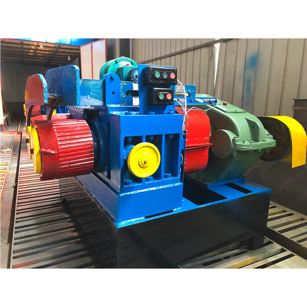
5. The structure of the machine
The machine is composed of frame, vertical shaft, bowl, horizontal shaft, collecting cover, electrical and other parts. Its structure is shown in Fig. 1, Fig. 2 and Fig. 3. There are two staring modes of the machine: friction start and frequency conversion start. The motor drives the large spiral gear of the horizontal shaft to rotate through the friction clutch or coupling, and the large spiral gear and the small spiral gear of the vertical shaft mesh to drive the vertical shaft and the bowl to rotate. The bowl is the separation function part of the separator, which is a non hole type disc group structure. The main purpose of the centrifugal friction clutch is to make the bowl accelerate slowly when starting, so as to reduce the starting current of the motor.
The upper support of the vertical shaft is equipped with a set of shock absorption springs to absorb the vibration generated by the rotation of the bowl
Square has a self-aligning bearing, the top has elastic spherical support, can make the vertical shaft automatic alignment, so that the normal operation of the machine.
There are 12 small springs above the vertical shaft, which are used to absorb the vibration of up and down direction.
The whole machine is placed on four groups of vibration damping rubber pads, which can absorb the vibration generated when the machine is running.
The separator is equipped with counting device to check the speed.
An electromagnetic brake is installed on the housing seat, which can stop the bowl in a short time.

5.1 Structure, disassembly and assembly of bowl parts:
The structure of the bowl is shown in Figure 4.The disassembly and assembly of the bowl must be carried out after the vertical shaft is lifted out.
a. The disassembly and installation sequence of the bowl is shown in Fig. 5. The disassembled parts must be cleaned before installation. In the same workshop, if there are several machines of the same type, do not confuse the parts when disassembling, so as to avoid machine vibration and even damage accidents.
b. During assembly, the guide position of parts should be confirmed to avoid damaging the guide.
c. The nut of the bowl is a left thread, which should be disassembled on the tool (attached with 24-0). First press the bowl cover tightly, then screw it anticlockwise with a tool (attached 1-0), and then screw the bowl nut with a tool (attached 24-0) until it is aligned with the relative mark dia. on the bowl cover. However, if the contact surface between the bowl cover and the bowl body can be completely contacted with only tools (attached with 1-0), spare discs should be added to increase the pressure.
d. After the bowl is installed on the vertical shaft, it should rotate freely, and the next step of assembly can only be carried out when there is no collision and other noise.
5
Данные ресурс не является интернет-магазином, а лишь содержит ссылки на международную торговую площадку Alibaba.com