Profibus Dp протокол модуль интегральная плата для привода
- Категория: Запчасти и аксессуары для инструментов >>>
- Поставщик: Microcyber,Corporation
Поделиться:
Описание и отзывы
Трекер стоимости
| Месяц | Минимальная цена | Макс. стоимость |
|---|---|---|
| Aug-20-2025 | 113.10 $* | 115.13 $* |
| Jul-20-2025 | 92.41 $* | 94.72 $* |
| Jun-20-2025 | 111.78 $* | 113.69 $* |
| May-20-2025 | 110.39 $* | 112.76 $* |
| Apr-20-2025 | 88.22 $* | 90.39 $* |
| Mar-20-2025 | 109.35 $* | 111.25 $* |
| Feb-20-2025 | 108.8 $* | 110.64 $* |
| Jan-20-2025 | 107.40 $* | 109.75 $* |
Характеристики
Product Description

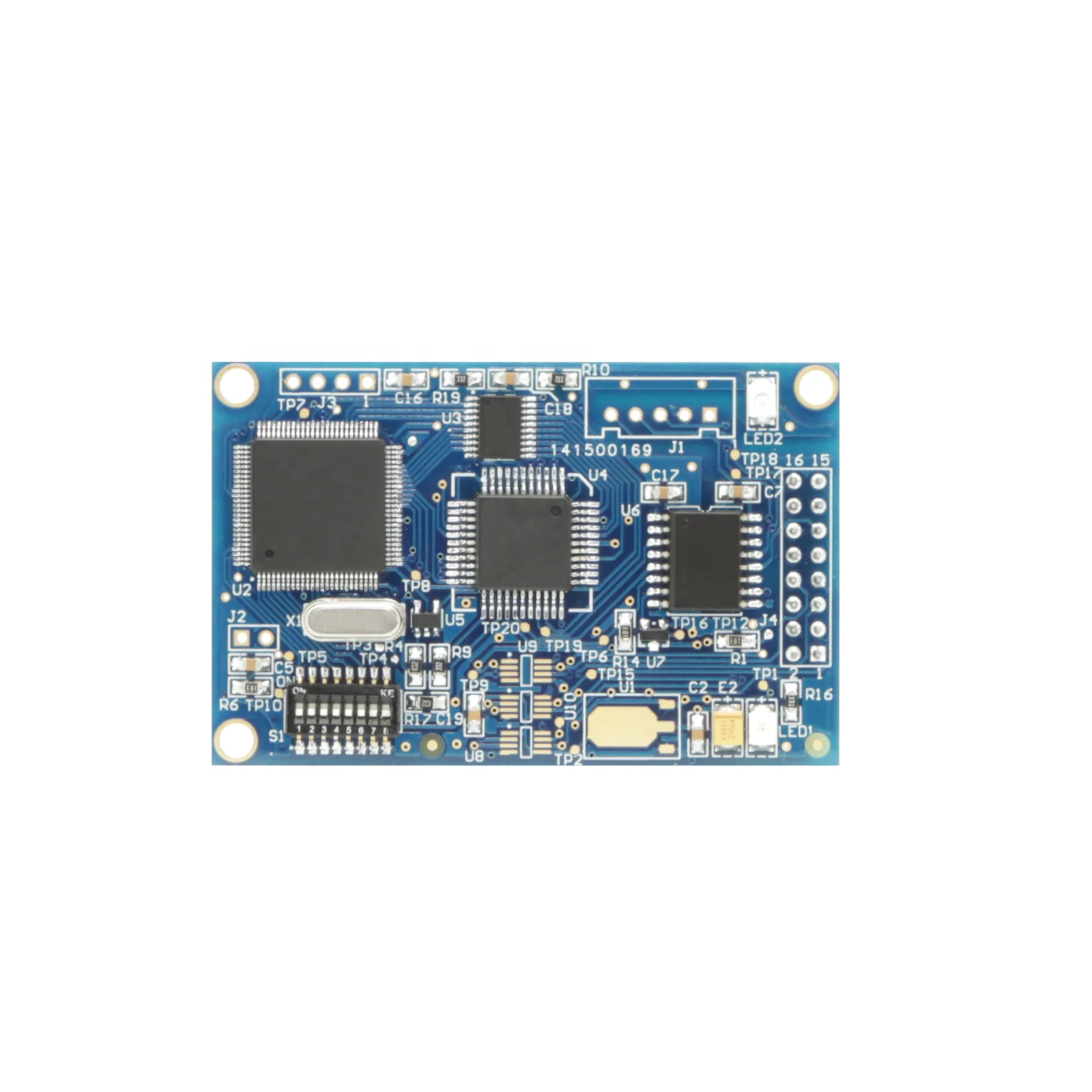
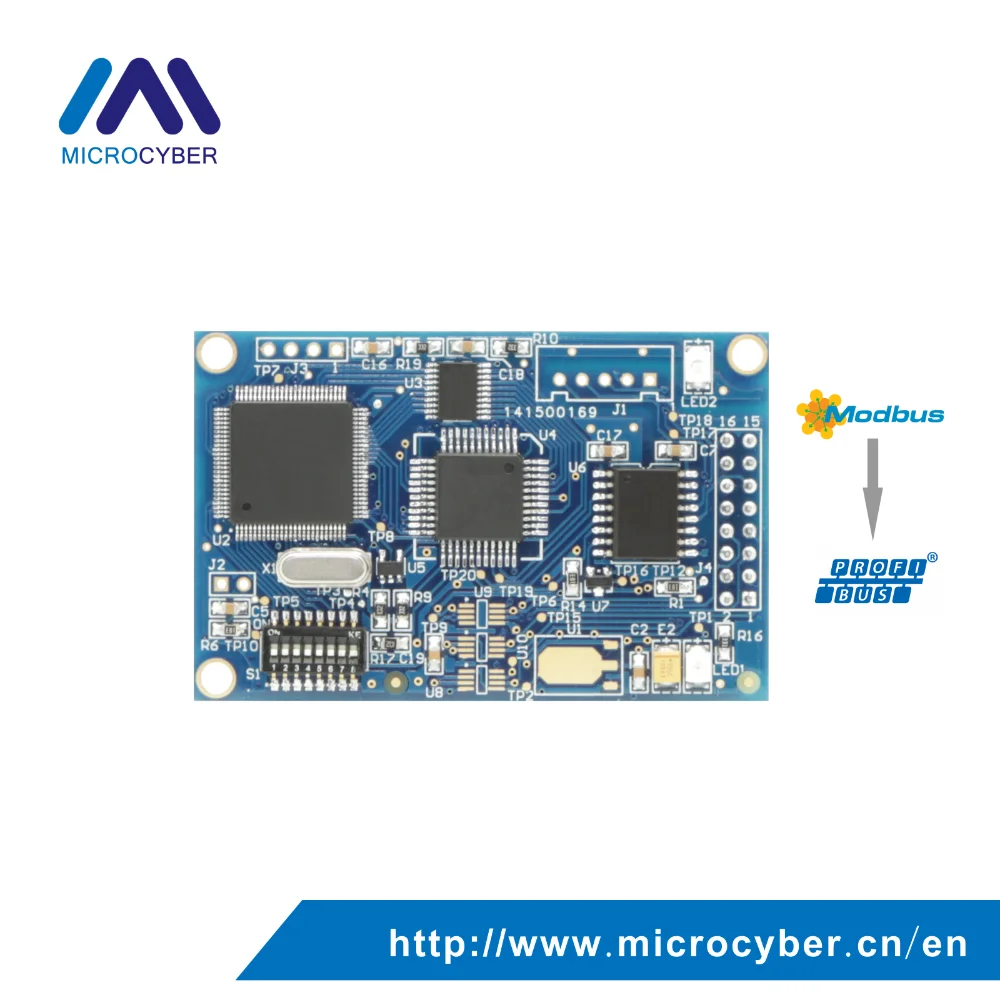
Modbus-DP built-in module realizes the connection from Modbus RTU device to PROFIBUS DP network .It realizes the conversion function from MODBUS Protocol to PROFIBUS DP Protocol. Only by simply operating Modbus configuration tool, the users can realize connection from Modbus RTU device to PROFIBUS DP network.
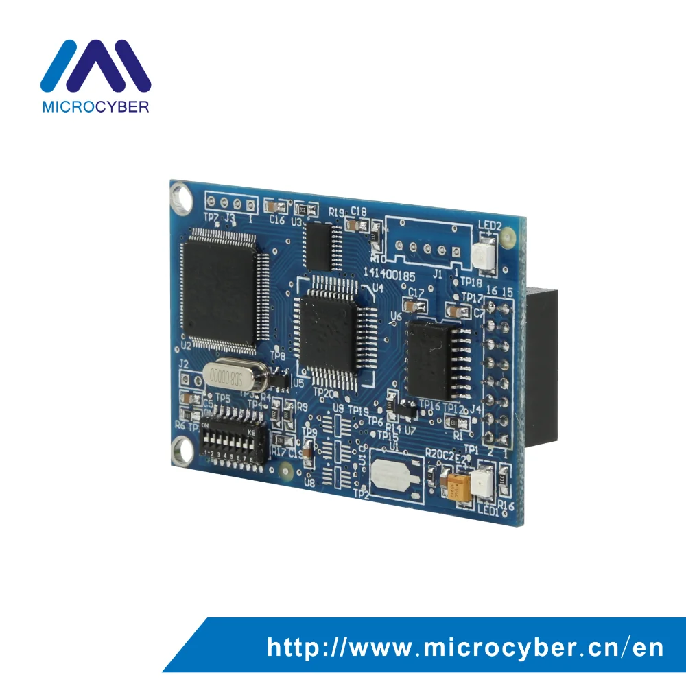
M0306 module works with DIP16 2.54mm standard interface, 3.3 V power supply, Modbus communication indicating light to quick diagnosis the device status. It uses simple convenience
Combining with the features of high reliability and high flexibility, M0306 module is an ideal choice for user to develop OEM devices with PROFIBUS DP protocol.


1)Short development period:
The user doesn’t need to understand PROFIBUS developing technology, doesn’t need to purchase PROFIBUS development system, also doesn’t need to compile GSD file, PROFIBUS product with intellectual property will be developed in short time;
2)Same size:
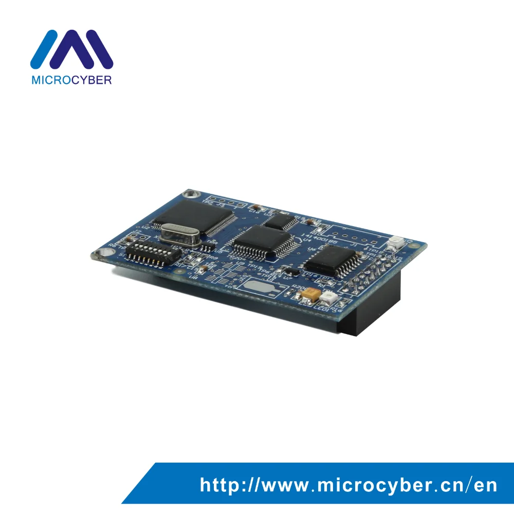
Microcyber M-series embedded modules have the same size, 65mm(length)*42mm(width).
3)Same interface:
Microcyber M-series embedded modules adopt 2.54 spacing 16 pin connector, with compatible function.
4)Easy to upgrade:\t
Replacement of Microcyber M-series different embedded modules can achieve different protocols of the device.
5)Flexible configuration:
Users can use Microcyber configuration tool to configure it, which is easy andconvenient to operate
6)Simple application:
MCU of user’s product read (write) input/output data into communication module by serial port. The communication module automatically transfers them into the communication between PROFIBUS-DP data and PROFIBUS master station;
7)Wide application:
Widely used onto all kinds of products, such as transducer, motor startup protection device, smart high-low-voltage electrical appliance, power measurement device, various transmitters, smart field measurement equipment, and instrumentation, etc.
8)Provide based on OEM:
The user has independent intellectual property rights, brand and trademark registration right.

Specifications
Basic Parameter | ||
Power | VCC(MCU power):5.0V 120mA / 3.3V 100mA | |
DP bus baud rate | Baud rate self- adaption:9.6K~12Mbps | |
Protocol before transition | Modbus GB/Z 19582.1-2004 | |
Protocol after transition | Profibus DP GB/T 20540.1~.6-2006 | |
DP max input data | Max Input Bytes ≤ 244 Bytes | |
DP max output data | Max Output Bytes ≤ 244 Bytes | |
DP max total input and output data | Input Bytes + Output Bytes ≤ 360 Bytes | |
max user data | Max User Data Bytes ≤ 200 Bytes | |
Max IO configuration data | Max IO Configuration Data Bytes ≤ 20 Bytes | |
Temperature range | -40℃ ~ +85℃ | |
Humidity range | 5 ~ 95%RH | |
Start time | ≤ 5s | |
Weight | 14 g | |
Dimension (L×W×H) | 65×42×14 mm | |
Electromagnetic compatibility | GB/T 18268.1 | |
Noise interference | EN 61131-2:2003 | |
Support Modbus Function Code | ||
01H | read coil state | |
02H | read input state | |
03H | Read holding register | |
04H | Read input register | |
05H | Set single coil | |
06H | Preset single register | |
0FH | Force various coils | |
10H | Preset various regsters | |
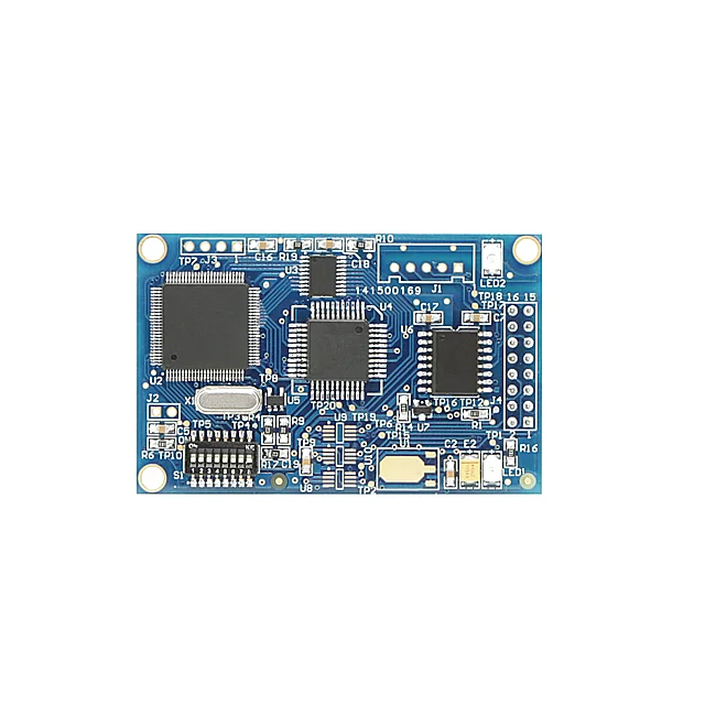
Installation
Module External Interface
Pin Definition and Instruction of User Interface 1(J4)
The user interface provides the module with one signal isolated DC power supply, serial interface between the two boards, as well as indicator lights and other functions. The specific description is shown in table Table 2.1.
The user interface provides the module with one signal isolated DC power supply, serial interface between the two boards, as well as indicator lights and other functions. The specific description is shown in table Table 2.1.

As shown in picture, user interface 1 uses 16-pin connector, specific pins are defined as follows:
Pin | I/O | Description | Pin | I/O | Description |
1 | I | VCC(5.0V / 3.3V DC) | 2 | O | VCC grounding |
3 | I | CPU Reset, Low Valid | 4 | I/O | Reserved |
5 | O | CPU serial data transmission | 6 | I/O | Reserved |
7 | I/O | Reserved | 8 | I | CPU serial data acceptance |
9 | O | Connect No.4 pin of PROFIBUS DP D type socket | 10 | O | DP communication state indication |
11 | I/O | Connect No.3 pin of PROFIBUS DP D type socket | 12 | I/O | Connect No.8 pin of PROFIBUS DP D type socket |
13 | I/O | Reserved | 14 | I/O | Reserved |
15 | I | 5V isolation power supply | 16 | O | 0V(isolation power supply grounding, isolated with GND) |
Dial Switch(S1)

No. | Name | Description |
1 | 1 | If ON,address+1,if not,addres+0. |
2 | 2 | If ON,address +2,if not,address +0. |
3 | 4 | If ON,address +4,if not,address +0. |
4 | 8 | If ON,address +8,if not,address +0. |
5 | 16 | If ON,address +16,if not,address +0. |
6 | 32 | If ON,address +32,if not,address +0. |
7 | 64 | If ON,address +64,if not,address +0. |
8 | M | M0306 working mode setting,ON is configuration mode, and OFF is normal working mode. |
Module Installation
M0306 has three Φ3 location hole and it can be fixed to user board with three hexagonal prisms (height 11mm) to fix.


Working Principle
M0306 supports one to one embedded connection with the RTU Modbus user board. The main function is to connect the user board to the PROFIBUS network, making it become PROFIBUS DP slave device. M0306 system connection diagram is shown in picture

M0306 module can complete the protocol conversion between PROFIBUS and Modbus, to achieve mapping and transparent transmission between user board Modbus input and output data and PROFIBUS master control system input and output data. The working principle of M0306 is shown in picture.

Working Mode
M0306 supports two modes of operation: configuration mode and normal operation mode, which can be switched in real-time according to the dial switch.
When M0306 works in configuration mode, M0306 is used as the Modbus slave station, while the Modbus general configuration tool is used as the Modbus master station. Through the Modbus general configuration tool, besides the configuration of basic information such as manufacturer ID, device ID and device address sources, themain function is the configuration of read-write user board Modbus input and output data’s Modbus command queue parameter information, such as which MODBUS function code are used by parameters to read and write, what the register address is and so on.
After the configuration, the information will be downloaded to the M0306. Under normal operating mode, M0306 is master station in Modbus side, the user board is Modbus slave station. In accordance with configured parameters and mechanisms, M0306 circularly sends Modbus command queue to the user board to read and write user board Modbus input and output data.
M0306 is DP slave station at the PROFIBUS terminal, conducting real-time PROFIBUS input and output data exchange with PROFIBUS master control system.
Modbus Data and PROFIBUS Data Mapping
The main function of M0306 module is to realize the mapping and transparent transmission between user board Modbus input and output data and PROFIBUS master control system input and output data. The specific data mapping relation is shown in picture.

During the usage of module, user can realize the I/O data exchange between module and user board through the specific configuration of the Modbus command. the I/O data store address correspondence in PROFIBUS master system is related with "I/O configuration identifier", and also the specific type of PROFIBUS master station system. Specific module configuration and application methods will be introduced in the fourth chapter. The following is example of SIEMENS S7-300 series PLC master system to introduce the I/O data address mapping between user board and the PROFIBUS master system.
Application

COMPANY PROFILE


FAQ

Q: Can I get a free electronic manual?
A: Yes, if you want it, please contact us.
Q: How are modules configured and used?
A: Before starting the normal operation mode, user needs to configure M0306 by configuration mode. The method is as follows:
1) Set module dial switch S1.8 bit to ON, making the module power on;2) Through the TTL to the serial port device, connect the module to computer serial port;
3) Install and open the Modbus general configuration tool, add the device by adding the serial port;
Q: Can you provided OEM service?
4) After scanning the device, the basic parameters of the device information will be read to the general configuration tool. Next, the user can refer to the specific needs of the configuration parameters to modify module;
5)Save the configuration. User can save a configuration file via configuration parameters saving function after configuration parameters, download the saved configuration file before batch configuration of various modules, with other working parameter modules for batch download.
Q: Can you provided OEM service?
A: Yes, we can, such as communication board, we can also provided fieldbus development toolkit.