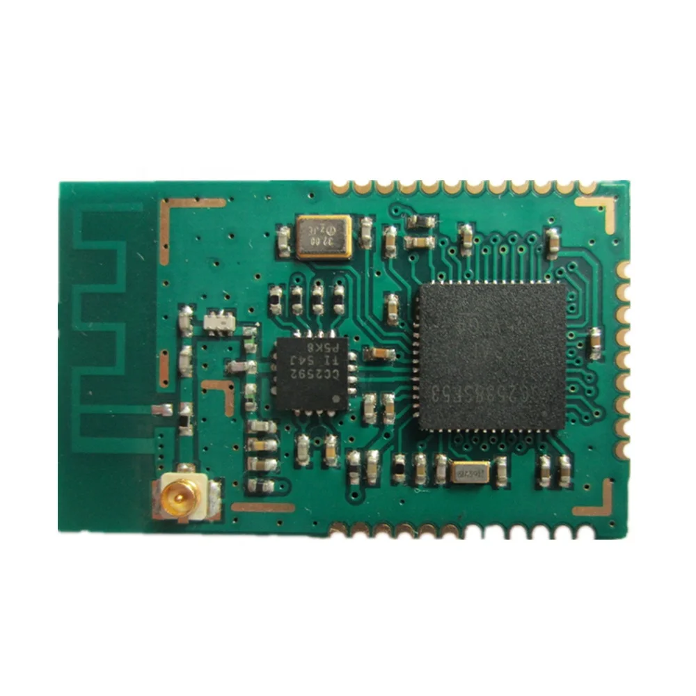
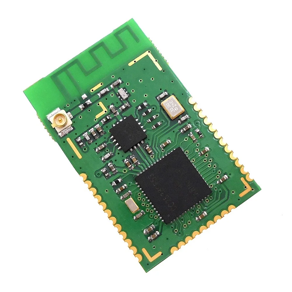
1. CC2538 chip. ARM core, rich hardware resources;
2. Frequency 2.4GHz, long communication distance, high anti-interference ability, transmission rate up to 250kbps.
3. Good wireless performance, low harmonics, full compliance with the certification requirements;
4. Low power consumption, easy control to low power mode;
5. Small size, light weight, size 21×32m, and main board soldering method;
6. All high-quality components are used, and the crystal oscillator uses MOTO and MICRO crystal oscillators. The reliability is very good.
7. Provide PCB antenna, IPEX antenna connection base 2 kinds of antenna connection.
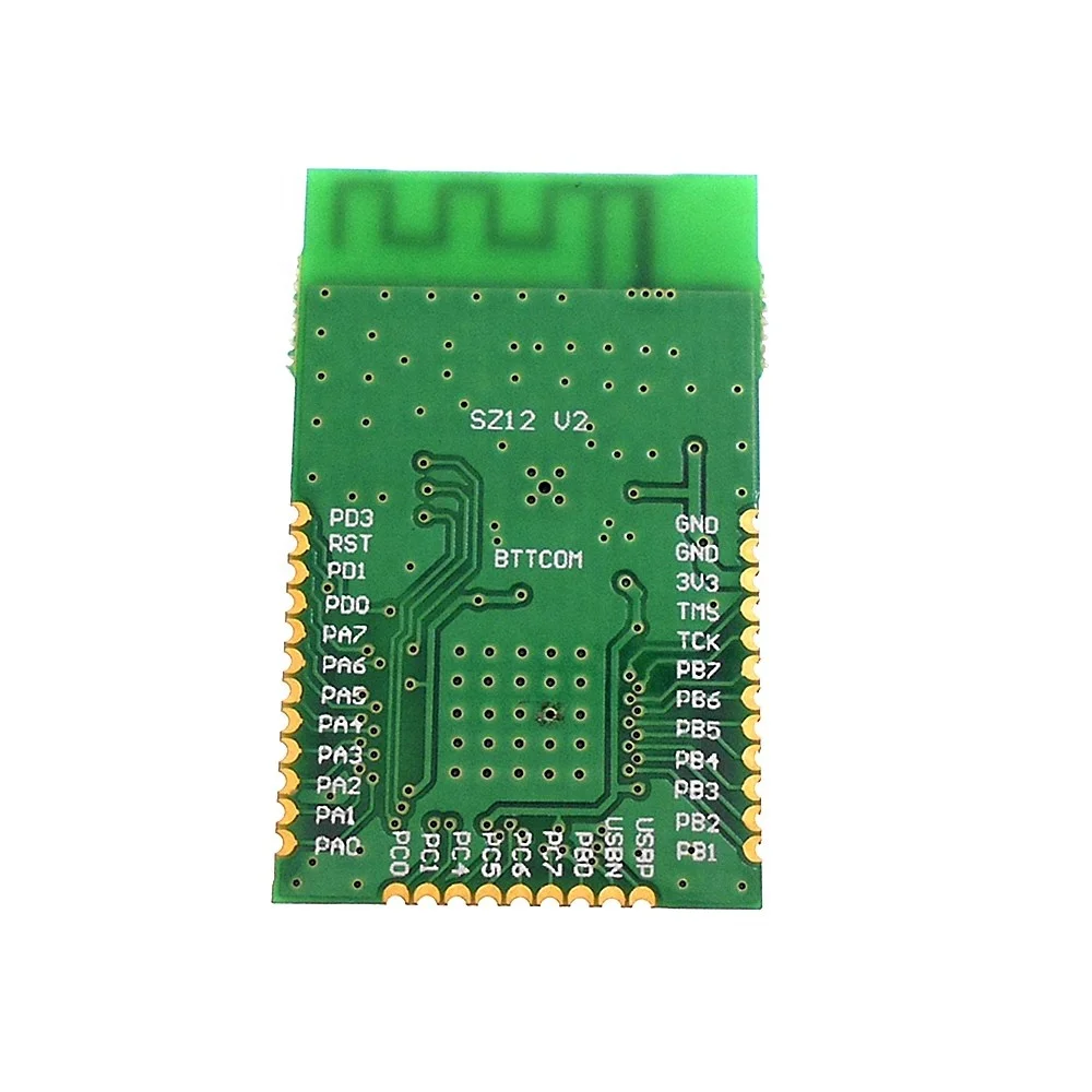
Pin description:
Sensitivity: -103.5dBm
Output power: +20dBm
Input gain: 12dB
Noise: 4dB
Emission current: <175mA
Receiving current: 30mA
Sleep current: 0.4uA
Operating voltage: 3.3V
Transmission distance: 600m
Data rate: 250Kbps
Number of channels: 16
Antenna: PCB or IPEX
Temperature range: -40°C~80°C
Module size 21×33m Pin spacing 1.27mm
Explanation:
1. Optional external IPEX-SMA antenna or PCB antenna;
2. PC2, PC3, PD2 are used for CC2592 control, not led out; PD4, PD5 are not led out
3. Pin signals are marked on the back of the module;
Pin size and PCB drawing
PA control pin description
(1) The pins of PC2, PC3, PD2 are for PA use, they are not led to the module IO, do not use
(2) PD4 and PD5 are not led out.
Instructions for use
1) It is recommended to set the output power of CC2538 to + 3dBm, at this time the output power of the entire module reaches about + 20dBm.
2) The module can be pinned or soldered directly to the PCB of the product. If a PCB antenna is used, under the PCB antenna
There must not be any traces or copper clad. There should be no metal or magnet materials around the PCB antenna.
3) The standard SZ12 module comes with a PCB printed board antenna, including an IPX antenna base, and the default transmitting antenna is PCB
antenna. Users can choose IPEX-SMA double-headed feeder, external SMA antenna, this mode is suitable for
The module is installed in a strong shielding case, and the antenna is placed outside the case. When using this mode, it needs to be broken
Open the PCB antenna connection, and guide the RF signal to the IPEX seat.
The power supply voltage is + 3,3V, make sure the output current is> 175mA.
Minimum system circuit:
J1 is the emulator interface, the emulator XDS100V3 produced by our company. When the emulator is used for power supply, R is not disconnected. If you use the 2-wire cJTAG interface, disconnect R7, R8, use the 4-wire JTAG interface, do not disconnect R7 , R8 ..
C is the power supply filter capacitor, its value is generally 33 ~ 100uF, it is best to use tantalum capacitor ..
The reset circuit is already in the module, and no components are needed on the periphery, but if the RST lead is long, it is recommended to add a filter circuit close to the module.